


Geometries with no orientation support
Chapter 3
Rockwell Automation Publication MOTION-UM002F-EN-P - February 2018
103
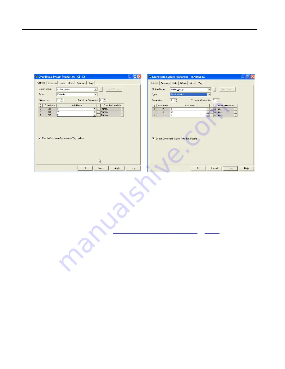
•
Configure the source and the target coordinate system with a transform
dimension of two.
•
The linear axis configured as a third axis must be the same for both the
source and target coordinate systems.
Calibrate a SCARA Delta robot using the same method for calibrating a Delta
three-dimensional robot. For more information about calibration, see Calibrate a
Delta Three-dimensional Robot.
See also
Calibrate a Delta Three-dimensional Robot
The work envelope for a SCARA Delta robot is similar to the two-dimensional
Delta robot in the X1-X2 plane. The third linear axis extends the work region
making it a solid region. The maximum positive and negative limits of the linear
axis defines the height of the solid region.
It is recommended to program the SCARA Delta robot within a rectangular solid
defined inside the work zone of the robot. Define the rectangular solid by the
positive and negative dimensions of the X1, X2, X3 virtual source axes. Be sure
that the robot position does not go outside the rectangular solid. Check the
position in the event task.
To avoid problems with singularity positions, the Logix Designer application
internally calculates the joint limits for the Delta robot geometries. For more
information about maximum positive and negative joint limits, see Maximum
positive joint limit condition and Maximum negative joint limit condition.
Calibrate a SCARA Delta robot
Identify the work envelope for
a SCARA Delta robot