


Geometries with orientation support
Chapter 4
Rockwell Automation Publication MOTION-UM002F-EN-P - February 2018
193
In the Delta robot, the End plate is always parallel to the Base plate and the 5-axis
Delta robot can reach up to limited orientation positions. Work and Tool frame
offset values are limited up to reachable work envelope. The following offset values
are allowed for Work and Tool frames. The MCTO instruction generates error
148 for invalid offset values.
•
Offset values on X, Y, Z and Rz axis are allowed for the Work Frame offsets.
Rx and Ry offsets are restricted and must be set to 0 . Specify these offsets
through the
WorkFrame
parameter in the MCTO instruction.
•
Offset values on X, Y, Z and Ry axis are allowed for the Tool Frame offsets.
Rx and Rz offsets are restricted and must be set to 0 . Specify these offsets
through the
ToolFrame
parameter in the MCTO instruction.
See also
Identify the Work Envelope for Delta J1J2J3J4J5 robot
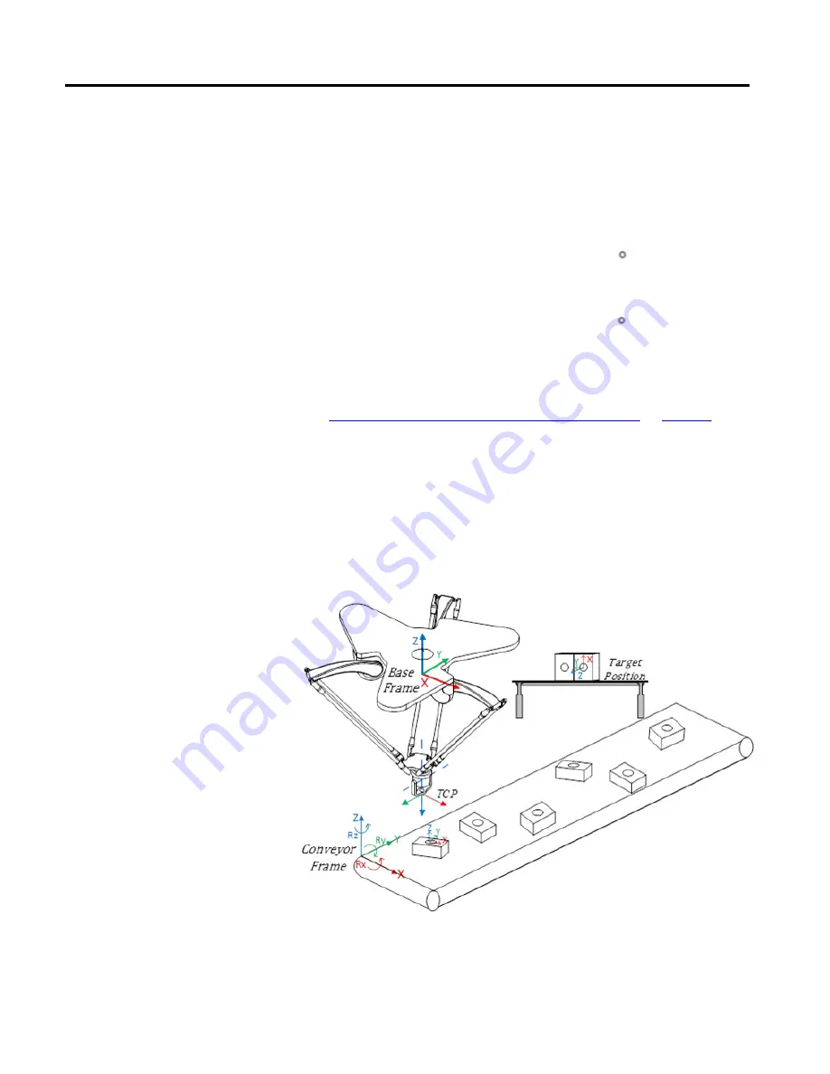
The following image is an example of a typical pick and place application with the
Delta robot. It illustrates how the 5-axis Delta robot picks up the boxes from the
conveyor and places them on the table with different orientations on Ry and Rz
axis, assuming that all target positions are reachable for the 5-axis Delta robot.
Conveyor coordinate system frame is used as a reference frame for this application.
Positions of all boxes on the conveyor are measured using this reference frame.
Work Frame offsets set the distance from the robot’s base frame to the conveyor
reference frame. For example, if the XYZ offsets between robot base frame to
conveyor reference frame is (-200, -100, and -1000) and the orientation offset on
Example of a Pick and Place
application for Delta J1J2J3J4J5
robot