


Chapter 5
Configure Camming
216
Rockwell Automation Publication MOTION-UM002F-EN-P - February 2018
•
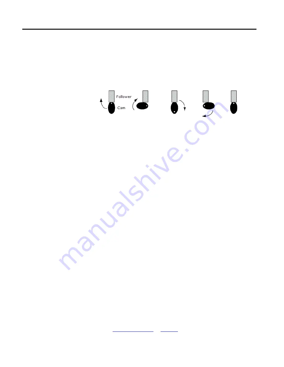
There is a physical connection between the cam and the follower.
•
The follower conforms to the cam shape as the cam unit rotates.
•
Motion is limited by the cam shape.
The following illustrates a mechanical cam turning in a clockwise manner and the
affect it has on a follower that is physically connected to it.
Electronic camming is an electronic replacement for a mechanical camming. In
this case, there is still a master axis that produces variable and reciprocating
motion in a slave axis. However, electronic camming coordinates the movement of
the two separate axes without a physical connection between them. There is no
physical cam or follower assembly. In addition to removing the physical
connection between axes, electronic camming:
•
Creates coordinated motion profiles that are functions of the time o relative
position of another axis.
•
Allows you to configure higher cam velocities.
•
Is defined by using a ‘point pair’ table of values. This table is a master axis set
of point positioning values and a corresponding set of slave axis point
positioning values.
The user-defined position point array causes one closed-loop axis to move with
another open or closed-loop axis.
A cam profile is a representation of non-linear motion, that is, a motion profile
that includes a start point, end point, and all points and segments in between. A
cam profile is represented by an array of cam elements. The point pair used in a
cam profile determines slave axis movement in response to master axis positions or
times.
In a motion control application, you can use two different types of general cam
profiles to accomplish electronic camming:
•
Position Cam Profile
•
Time Cam Profile
See also
Electronic camming
Cam Profiles