


Chapter 1
Create and configure a coordinate system
34
Rockwell Automation Publication MOTION-UM002F-EN-P - February 2018
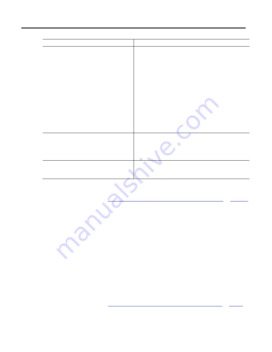
Parameter
Description
Master Delay Compensation
Determines whether to enable or disable Master Delay Compensation.
The Master Delay Compensation is used to balance the delay time between reading the
Master Axis command position and applying the associated slave command to the slave's
servo loop.
It ensures that the slave coordinate command position accurately tracks the actual position
of the Master Axis (that is, zero tracking error when gearing or camming to the actual
position of a Master Axis for Cartesian coordinate motion in Master Driven mode).
Clear the check box to disable Master Delay Compensation.
Tips:
•
If the axis is configured for Feedback only, disable Master Delay Compensation.
•
In some applications, there is no requirement for zero tracking error between the Master
and the Slave axis. In these cases, it may be beneficial to disable Master Delay
Compensation to eliminate the disturbances introduced to the Slave Axis.
•
Master Delay Compensation, even if it is enabled, is not applied in cases where a Slave
Axis is gearing or camming to the Master Axis’s command position because there is no
need to compensate for master position delay.
Enable Master Position Filter
Determines whether to enable or disable Master Position Filter.
The Master Position Filter filters the specified master axis position input to the slave axis’s
gearing or position camming operation. The filter smooths out the actual position signal
from the Master Axis, and thus smooths out the corresponding motion of the Slave Axis.
Select the check box to enable the Master Position Filter.
Master Position Filter Bandwidth
The bandwidth used for master position filter.
This parameter is only available when Master Position Filter is enabled.
Tip:
Entering a zero also disables the Master Position Filter.
See also
Coordinate System Properties dialog box - Motion Planner tab
How do I open the Tag tab?
1.
In the
Controller Organizer
, expand the
Motion Group
folder, and
double-click the coordinate system.
2.
On the
Coordinate System Properties
dialog box, click the
Tag
tab.
Use the settings on the
Tag
tab in the
Coordinate System Properties
dialog box
to modify the name and description of the coordinate system. When the
controller is online, the parameters are read-only.
Tip:
Save your changes before going online. Otherwise, pending changes revert to their
previously-saved state.
See also
Coordinate System Properties dialog box - Tag tab parameters
Coordinate System Properties
dialog box - Tag tab