


Chapter 3
Geometries with no orientation support
102
Rockwell Automation Publication MOTION-UM002F-EN-P - February 2018
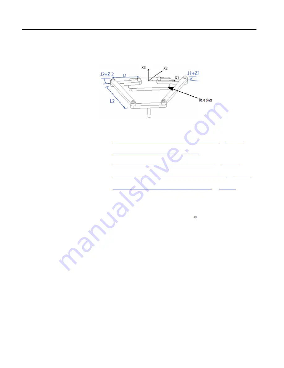
The SCARA Delta robot geometry is similar to a two-dimensional Delta robot
geometry except that the X1-X2 plane is tilted horizontally with the third linear
axis in the vertical direction (X3).
See also
Establish the reference frame for a SCARA Delta robot
Identify the work envelope for a SCARA Delta robot
Define configuration parameters for a SCARA Delta robot
Configure a Delta robot with a Negative X1b offset
The reference frame for the SCARA Delta robot is located at the center of the
base plate.
When the angles of joints J1 and J2 are both at 0 , the two L1 links is along the
X1 axis. One L1 link is pointing in the positive X1 direction, the other in the
negative X1 direction.
When the right-hand link L1 moves in the clockwise direction (looking down on
the robot), joint J1 is assumed to be rotating in the positive direction. When the
right-hand link L1 moves counterclockwise, joint J1 is assumed to be moving in
the negative direction.
When left-hand link L1 moves in the clockwise direction, joint J2 is assumed to be
moving in the negative direction. When the left-hand link L1 moves in the
counterclockwise direction, joint J2 is assumed to be rotating in the positive
direction.
Based on the right hand rule, X3 positive will be orthogonal to the X1-X2 plane
pointing up. The linear axis will always move in the X3 direction.
When configuring a SCARA Delta robot in the Logix Designer application,
observe these guidelines:
Configure a SCARA Delta
robot
Establish the reference frame
for a SCARA Delta robot