


Cartesian coordinate system
Chapter 2
Rockwell Automation Publication MOTION-UM002F-EN-P - February 2018
57
The Logix Designer application compares
To the
And uses the
For the
100% of the configured length of the first instruction
using a Command Tolerance termination type
configured Command Tolerance for
the Coordinate System
shorter of the two lengths
command Tolerance length used for
the
first
instruction
100% of the configured length of the last move
instruction using a Command Tolerance termination
type
configured Command Tolerance for
the Coordinate System
shorter of the two lengths
command Tolerance length used for
the
next to last
instruction
50% of each of the lengths of all other move instructions configured Command Tolerance for
the Coordinate System
shorter of the two lengths
command Tolerance length used for
each individual
instruction
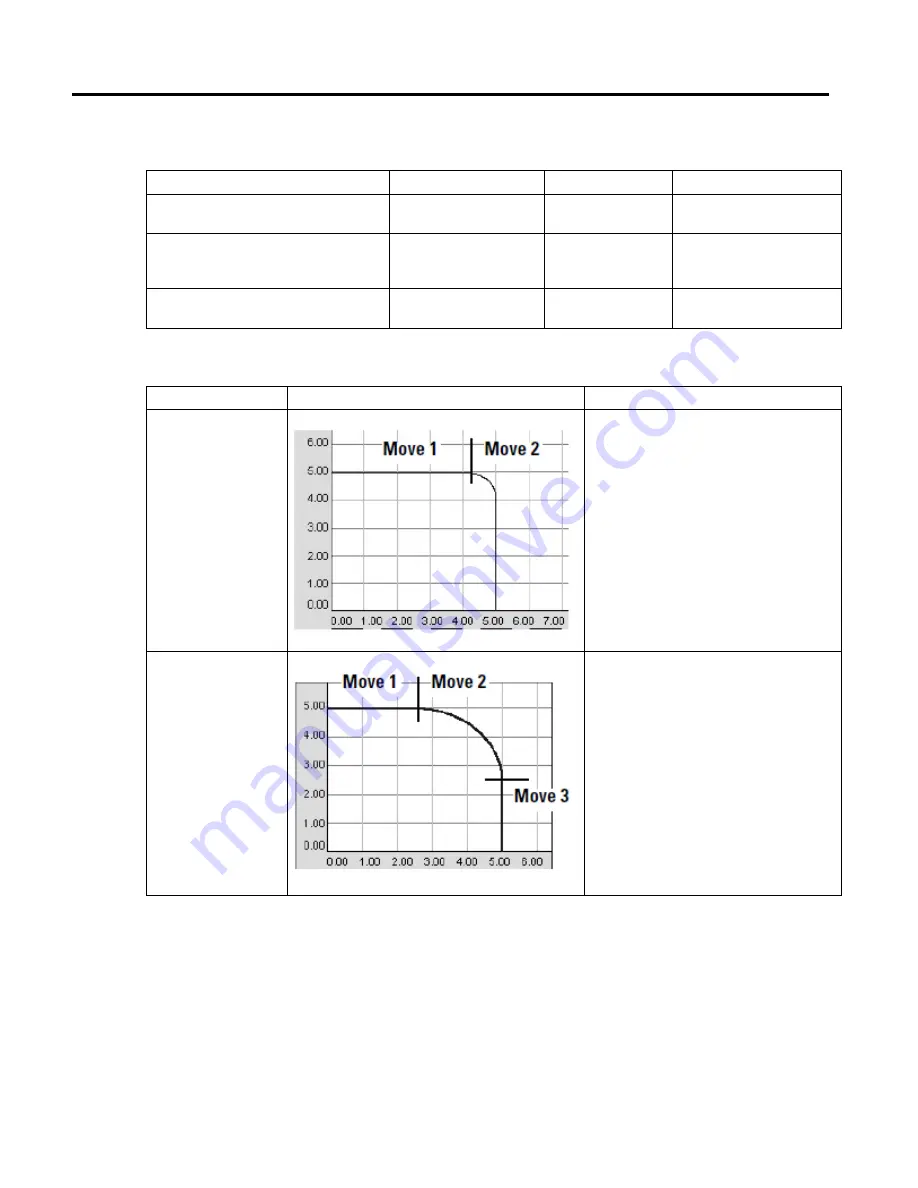
Termination Type
Example Path
Description
3 - No Decel
The instruction stays active until the axes get to the
deceleration point. At that point, the instruction is
complete and a queued MCLM or MCCM instruction can
start.
•
The deceleration point depends on whether you use a
trapezoidal or S-curve profile.
•
If you don’t have a queued MCLM or MCCM instruction,
the axes stop at the target position.
4 - Follow Contour Velocity
Constrained
The instruction stays active until the axes get to the target
position. At that point, the instruction is complete and a
queued MCLM or MCCM instruction can start.
•
This termination type works best with tangential
transitions. For example, use it to go from a line to a
circle, a circle to a line, or a circle to a circle.
•
The axes follow the path.
•
The length of the move determines the maximum speed
of the axes. If the moves are long enough, the axes will
not decelerate between moves. If the moves are too
short, the axes decelerate between moves.