


Geometries with orientation support
Chapter 4
Rockwell Automation Publication MOTION-UM002F-EN-P - February 2018
143
•
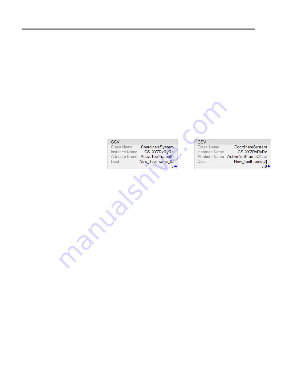
ActiveToolFrameID
and
ActiveToolFrameOffset
attributes reflect the
information specified in the tool frame operand when the MCTO
instruction activates.
•
When the MCTO instruction executes,
Tool Frame ID
and
Tool Frame
Offset
members of the
Tool Frame
operand of the MCTO instruction are
copied to the
ActiveToolID
,
ActiveToolOffset
members of the source
coordinate system as specified in the MCTO instruction.
•
ActiveToolFrameID
is set to default value as -1 when no tool frame is
active. It also resets to this value when transform instruction terminates.
The
ActiveToolFrameOffset
values are cleared when the transform
instruction terminates.
•
These two attributes of the coordinate system are exposed to the user
through the GSV instructions as shown in this image.
ToolChangeAllowedStatus
•
ToolChangeAllowedStatus
attribute allows the user to change the tool
dynamically through the MCTO instruction while coordinated moves are
finished or any source axis is in motion through the MAG or MAPC
instruction as a slave axis.
•
The
ToolChangeAllowed
bit is present in all coordinate systems, and it is
set in the source and target coordinate system of an
active MCTO
instruction.
•
The bit is set when the MCTO instruction goes IP. It is cleared when any
motion is active on source axis or target axis. The bit remains set when
output of MAG and MAPC generates motion on any axis associated with
source coordinate system of
active MCTO
instruction.
•
The ToolChangeAllowed bit is cleared when a MCTO instruction is
terminated for any reason, such as MCS, MGS, MGSD, MGSDR, MASR,
MASD, and MSF.
Restriction
In robot geometries, such as Delta robots, some of the tool frame orientation
offsets are restricted. This prevents programming the robot with unreachable
positions through the tool frame offsets.