


Chapter 4
Geometries with orientation support
198
Rockwell Automation Publication MOTION-UM002F-EN-P - February 2018
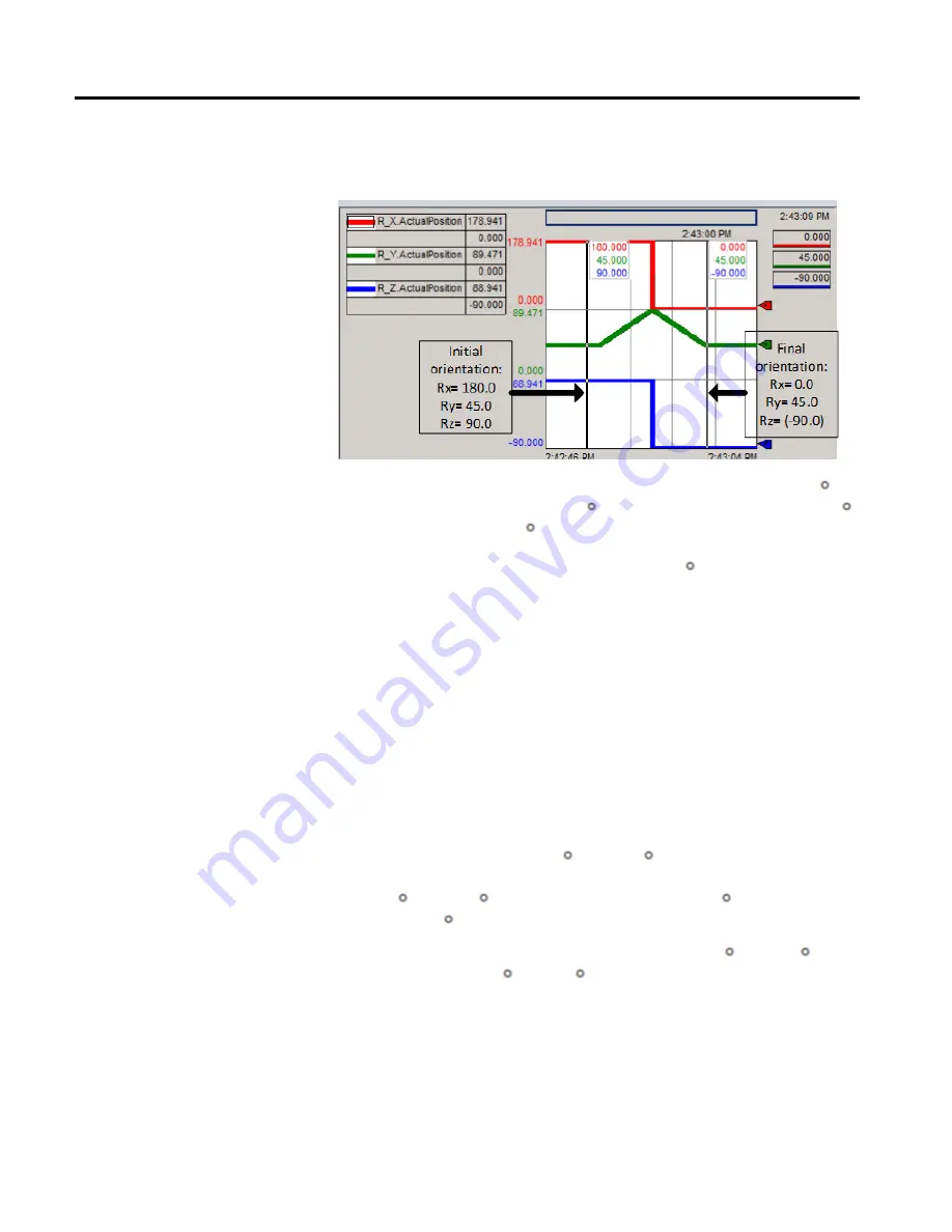
The following trend shows the Ry mirror image orientation and associated flip
behavior on Rx and Rz axes.
The move that is demonstrated in the example is a pure Ry move from 45.0 in
the mirror non-flip region (Rx = 180.0 ) in a positive direction ending at 45.0
in the rollover region (Rx = 0 ).
Tips:
•
The flip of Rx and Rz values as Ry crosses the mirror boundary at 90 .
•
No motion is commanded on Rx or Rz, only Ry.
Tip:
To use these Kinematic sample projects, on the
Help
menu, click
Vendor Sample Projects
and then click the
Motion
category.
The Rockwell Automation sample project's default location is:
c:\Users\Public\Public Documents\Studio 5000\Sample\ENU\v<current_release>\Rockwell Automation
The following orientation angle specifications are not allowed in Logix Designer
application due to singularity conditions involving multiple solutions or other
scenarios involving Euler angle specification:
•
The orientation [Rx = 180.0 , Ry = 90.0 ] is mathematically correct but is
not allowed in Logix Designer application due to ambiguity with the [Rx =
0.0 , Ry = 90.0 ] specification.
Always use Rx = 0.0 when specifying
Ry = 90.0
.
•
An absolute orientation move starting at [Rx = 180.0, Ry = 0.0 ] and
ending at [Rx = 0.0 , Ry = 0.0 ] is not allowed. See example 6 in Use
MCPM to program Ry absolute moves for geometries with mirror image
position.
•
Shortest rotary path moves for Ry is not allowed when both start and end
orientation lies in the mirror flip region. See example 6 in Use MCPM to
program Ry absolute moves for geometries with mirror image position.
Example of mirror image and
flip behavior on Rx and Rz axes
Mirror orientation restrictions