


Endura AZ30 series integral probe and remote transmitter
Combustion oxygen monitor
5 Electrical Installation
COI/AZ30E–EN Rev. D
27
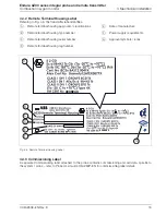
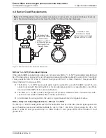
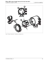
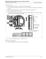
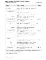
Referring to Fig. 5.7:
3.
Feed the incoming AC power supply cable through cable gland
A
.
4.
At terminal block
B
make connections to the AC power supply live (brown) and neutral (blue)
terminals.
5.
Connect the incoming AC power supply earth wire to internal earth connection
C
.
6.
Close the hinged power supply cover
C
.
7.
Feed the signal cable(s) through cable gland(s)
D
and make connections to the relay output(s),
current output and option terminals as required.
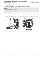
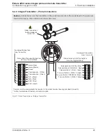
Referring to Fig. 5.6, page 26:
8.
Refit the transmitter rear cover
A
and tighten it hand-tight.
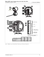
Fig. 5.7 Power and Output Signal Connections – Integral Transmitter
B
A
C
D
Option Board
Connections**
*Refer to Section 8.2, page 74 for
HART communication details
Current Output
4 to 20 mA HART*
Relay 1
Mains Power
Relay 2
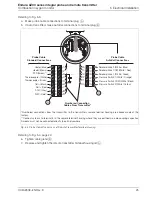
**Option Board Connections
Analog output
Digital I/O
A
+
DIO1
B
–
DIO2
C
COM
NC
C
NC
C
Spare
Earth


