Endura AZ30 series integral probe and remote transmitter
Combustion oxygen monitor
5 Electrical Installation
COI/AZ30E–EN Rev. D
29
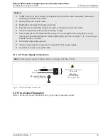
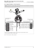
5.4.3 Integral Transmitter – Probe Connections
Caution.
Connections from the transmitter to the probe head and from the probe head to the probe are
made at the factory. This section is for information only.
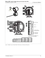
*Screens must be connected to the terminal in the remote terminal housing (not directly to earth).
**6-Way terminal block fitted only on AutoCal option.
Fig. 5.9 Probe Connections at Integral Transmitter
1
2
3
4
5
6
7
8
9
1
2
3
4
5
6
7
8
9
15
14
13
12
11
10
15
14
13
12
11
10
Probe Cable AutoCal Connections
to 6-way Terminal Block**
Probe Cable Standard Connections
to 9-way Terminal Block
Solenoid Valve 2 (White / Blue)
Solenoid Valve COM (White / Red)
Solenoid Valve 1 (White / Green)
Pressure Switch 1 (White / Orange)
Pressure Switch COM (White / Black)
Pressure Switch 2 (White / Yellow)
Heater (Blue)
Heater (Brown)
Screen*
Thermocouple – (White)
Thermo (Green)
Cell – (Black)
Cell + (Red)
ACJC (Grey)
ACJC (Violet)
Probe Connections
(behind probe lid)
265 V AC
Numbered Connections
From Transmitter
Numbered Connections
From Transmitter

