


connected to the drive's digital and analog inputs (typically low-voltage circuits) are
protected against contact and insulated with basic insulation from other low-voltage
circuits. The insulation must be rated for the same voltage level as the drive main circuit.
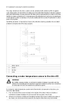
3.
You can connect the sensor to an extension module with basic insulation (eg. FAIO-01)
or reinforced insulation (eg. FPTC-xx) between the sensor connector and the other
connectors of the module. See the table below for the sensor insulation requirement.
For sensor connection to the extension module, see its manual.
4.
You can connect a sensor to an external thermistor relay the insulation of which is rated
for the same voltage level as the main circuit of the drive.
■
Drive I/O, I/O extension and encoder interface modules
See
•
section
AI1 or AI2 as a Pt100, Pt1000, PTC or KTY84 sensor input (page 134)
•
section
DI6 as a PTC sensor input (page 134)
•
FPTC-01 thermistor protection module (L536) for ACS880 drives user's manual
(3AXD50000027750 [English])
•
FPTC-02 ATEX-certified thermistor protection module Ex II (2) GD (L537+Q971)
for ACS880 drives user's manual
(3AXD50000027782 [English]).
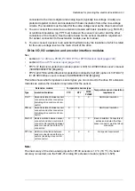
This table shows what temperature sensor types you can connect to the drive I/O extension
modules as well as the insulation requirement for the sensor.
Temperature sensor insulation
requirement
Temperature sensor type
Extension module
Pt100,
Pt1000
KTY
PTC
Insulation/Isolation
Type
Reinforced insulation
X
X
-
Galvanic isolation between sensor
connector and other connectors
(including drive control unit con-
nector)
FIO-11
Reinforced insulation
-
X
X
Galvanic isolation between sensor
connector and other connectors
(including drive control unit con-
nector)
FEN-xx
Basic insulation. Connectors of
extension module other than
sensor connector must be left un-
connected.
X
X
X
Basic insulation between sensor
connector and drive control unit
connector. No insulation between
sensor connector and other I/O
connectors.
FAIO-01
No special requirement
X
X
X
Reinforced insulation between
sensor connector and other con-
nectors (including drive control
unit connector)
FPTC-xx
Note:
The inaccuracy of the drive analog inputs for Pt100 sensors is 10 °C (18 °F). If a better
accuracy is needed, use the FAIO-01 analog I/O extension module (L525).
Guidelines for planning the electrical installation 93
Summary of Contents for ACS880-07
Page 1: ...ABB industrial drives Hardware manual ACS880 07 drives 560 to 2800 kW ...
Page 2: ......
Page 4: ......
Page 22: ...22 ...
Page 28: ...28 ...
Page 94: ...94 ...
Page 112: ...Electrical installation 109 5 6 4 3 112 Electrical installation ...
Page 113: ...110 Electrical installation 7 8 8 Electrical installation 113 ...
Page 114: ...Electrical installation 111 9 10 114 Electrical installation ...
Page 116: ...Electrical installation 113 4 5 3 6 7 116 Electrical installation ...
Page 118: ...2 11 b PE 10 7 5 6 8 a 360 grounding detail 118 Electrical installation ...
Page 128: ...128 ...
Page 146: ...146 ...
Page 148: ...148 ...
Page 159: ...12 Install and tighten the two M4 12 T20 screws 10 11 12 Maintenance 159 ...
Page 162: ...6 6a 6a 6b 7a 7b 7 8 8a 8b 162 Maintenance ...
Page 166: ...166 Maintenance 6 6 7 8 7 166 Maintenance ...
Page 173: ...6 Reinstall the cover removed earlier and close the cubicle door 4 4 D7T D8T Maintenance 173 ...
Page 213: ... Dimension drawing examples Frame 2 D7T 2 R8i 12 pulse A004 Dimensions 213 ...
Page 214: ...Frame 1 D8T 2 R8i IP22 214 Dimensions ...
Page 215: ...Frame 1 D8T 2 R8i IP54 B055 Dimensions 215 ...
Page 216: ...Frame 1 D8T 2 R8i with common motor terminal cubicle H359 1 2 216 Dimensions ...
Page 217: ...Frame 1 D8T 2 R8i with common motor terminal cubicle H359 2 2 Dimensions 217 ...
Page 218: ...Frame 1 D8T 2 R8i with brake choppers and resistors D150 D151 1 2 218 Dimensions ...
Page 219: ...Frame 1 D8T 2 R8i with brake choppers and resistors D150 D151 2 2 Dimensions 219 ...
Page 220: ...Frame 1 D8T 2 R8i with sine output filter E206 1 2 220 Dimensions ...
Page 221: ...Frame 1 D8T 2 R8i with sine output filter E206 2 2 Dimensions 221 ...
Page 222: ...Frame 2 D8T 2 R8i 12 pulse A004 with grounding switch F259 222 Dimensions ...
Page 223: ...Frame 2 D8T 3 R8i 1 2 Dimensions 223 ...
Page 224: ...Frame 2 D8T 3 R8i 2 2 224 Dimensions ...
Page 225: ...Frame 2 D8T 3 R8i with common motor terminal cubicle H359 1 2 Dimensions 225 ...
Page 226: ...Frame 2 D8T 3 R8i with common motor terminal cubicle H359 2 2 226 Dimensions ...
Page 227: ...Frame 2 D8T 3 R8i with top entry top exit H351 H353 1 2 Dimensions 227 ...
Page 228: ...Frame 2 D8T 3 R8i with top entry top exit 2 2 228 Dimensions ...
Page 229: ...Frame 3 D8T 4 R8i 1 2 Dimensions 229 ...
Page 230: ...Frame 3 D8T 4 R8i 2 2 230 Dimensions ...
Page 231: ...Frame 3 D8T 4 R8i with common motor terminal cubicle H359 1 2 Dimensions 231 ...
Page 232: ...Frame 3 D8T 4 R8i with common motor terminal cubicle H359 2 2 232 Dimensions ...
Page 233: ...Frame 3 D8T 4 R8i with top entry top exit H351 H353 1 2 Dimensions 233 ...
Page 234: ...Frame 3 D8T 4 R8i with top entry top exit H351 H353 2 2 234 Dimensions ...
Page 235: ...Frame 4 D8T 5 R8i 6 pulse with top entry exit UL Listed C129 1 2 Dimensions 235 ...
Page 236: ...Frame 4 D8T 5 R8i 6 pulse with top entry exit UL Listed C129 2 2 236 Dimensions ...
Page 237: ... Dimensions of empty cubicles options C199 C200 C201 IP22 IP42 Dimensions 237 ...
Page 238: ...IP54 238 Dimensions ...
Page 243: ... 1000 mm UL CSA top cable entry Dimensions 243 ...
Page 244: ... 1000 mm UL CSA bottom cable entry 244 Dimensions ...
Page 264: ...264 ...
Page 272: ... 272 ...


