


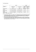


Connection: Dy 11 d0 or Dyn 11 d0
Transformer specification
for 12-pulse supply
(IEC 60076-1:2011)
Phase shift between secondaries: 30° electrical
Voltage difference between secondaries: < 0.5%
Short-circuit impedance of secondaries: > 5%
Short-circuit impedance difference between secondaries: ≤ 10% of the percentage
impedance
No grounding of the secondaries allowed. Static shield recommended.
Motor connection data
Asynchronous AC induction motors, permanent magnet synchronous motors and
AC induction servomotors, ABB synchronous reluctance (SynRM) motors
Motor types
0 to
U
1
, 3-phase symmetrical,
U
max
at the field weakening point
Voltage (
U
2
)
0…500 Hz (0…120 Hz with sine output filters (E206))
Frequency
• For higher operational output frequencies, please contact your local ABB repres-
entative.
• Operation above 150 Hz may require type-specific derating. For more information,
contact your local ABB representative.
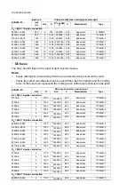
See the rating tables.
Current
3 kHz (typical). The switching frequency can vary per frame and voltage. For exact
values, please contact your local ABB representative.
Switching frequency
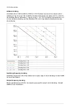
500 m (1640 ft).
Maximum recommended
motor cable length
Note:
With motor cables longer than 150 m (492 ft) the EMC Directive requirements may
not be fulfilled.
Control unit connection data
See chapter
Control units of the drive (page 129)
.
Efficiency
97.2 … 98.0% at nominal power level depending on drive type
Efficiency
Protection classes
IP22 (standard), IP42 (optional), IP54 (optional)
Degrees of protection
(IEC/EN 60529)
UL Type 1 (standard), UL Type 1 (B054), UL Type 12 (B055). For
indoor use only.
Enclosure types (UL50)
III
Overvoltage category
(IEC/EN 60664-1)
I
Protective class
(IEC/EN 61800-5-1)
Ambient conditions
Environmental limits for the drive are given below. The drive is to be used in a heated,
indoor, controlled environment.
Technical data 193
Summary of Contents for ACS880-07
Page 1: ...ABB industrial drives Hardware manual ACS880 07 drives 560 to 2800 kW ...
Page 2: ......
Page 4: ......
Page 22: ...22 ...
Page 28: ...28 ...
Page 94: ...94 ...
Page 112: ...Electrical installation 109 5 6 4 3 112 Electrical installation ...
Page 113: ...110 Electrical installation 7 8 8 Electrical installation 113 ...
Page 114: ...Electrical installation 111 9 10 114 Electrical installation ...
Page 116: ...Electrical installation 113 4 5 3 6 7 116 Electrical installation ...
Page 118: ...2 11 b PE 10 7 5 6 8 a 360 grounding detail 118 Electrical installation ...
Page 128: ...128 ...
Page 146: ...146 ...
Page 148: ...148 ...
Page 159: ...12 Install and tighten the two M4 12 T20 screws 10 11 12 Maintenance 159 ...
Page 162: ...6 6a 6a 6b 7a 7b 7 8 8a 8b 162 Maintenance ...
Page 166: ...166 Maintenance 6 6 7 8 7 166 Maintenance ...
Page 173: ...6 Reinstall the cover removed earlier and close the cubicle door 4 4 D7T D8T Maintenance 173 ...
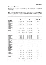
Page 213: ... Dimension drawing examples Frame 2 D7T 2 R8i 12 pulse A004 Dimensions 213 ...
Page 214: ...Frame 1 D8T 2 R8i IP22 214 Dimensions ...
Page 215: ...Frame 1 D8T 2 R8i IP54 B055 Dimensions 215 ...
Page 216: ...Frame 1 D8T 2 R8i with common motor terminal cubicle H359 1 2 216 Dimensions ...
Page 217: ...Frame 1 D8T 2 R8i with common motor terminal cubicle H359 2 2 Dimensions 217 ...
Page 218: ...Frame 1 D8T 2 R8i with brake choppers and resistors D150 D151 1 2 218 Dimensions ...
Page 219: ...Frame 1 D8T 2 R8i with brake choppers and resistors D150 D151 2 2 Dimensions 219 ...
Page 220: ...Frame 1 D8T 2 R8i with sine output filter E206 1 2 220 Dimensions ...
Page 221: ...Frame 1 D8T 2 R8i with sine output filter E206 2 2 Dimensions 221 ...
Page 222: ...Frame 2 D8T 2 R8i 12 pulse A004 with grounding switch F259 222 Dimensions ...
Page 223: ...Frame 2 D8T 3 R8i 1 2 Dimensions 223 ...
Page 224: ...Frame 2 D8T 3 R8i 2 2 224 Dimensions ...
Page 225: ...Frame 2 D8T 3 R8i with common motor terminal cubicle H359 1 2 Dimensions 225 ...
Page 226: ...Frame 2 D8T 3 R8i with common motor terminal cubicle H359 2 2 226 Dimensions ...
Page 227: ...Frame 2 D8T 3 R8i with top entry top exit H351 H353 1 2 Dimensions 227 ...
Page 228: ...Frame 2 D8T 3 R8i with top entry top exit 2 2 228 Dimensions ...
Page 229: ...Frame 3 D8T 4 R8i 1 2 Dimensions 229 ...
Page 230: ...Frame 3 D8T 4 R8i 2 2 230 Dimensions ...
Page 231: ...Frame 3 D8T 4 R8i with common motor terminal cubicle H359 1 2 Dimensions 231 ...
Page 232: ...Frame 3 D8T 4 R8i with common motor terminal cubicle H359 2 2 232 Dimensions ...
Page 233: ...Frame 3 D8T 4 R8i with top entry top exit H351 H353 1 2 Dimensions 233 ...
Page 234: ...Frame 3 D8T 4 R8i with top entry top exit H351 H353 2 2 234 Dimensions ...
Page 235: ...Frame 4 D8T 5 R8i 6 pulse with top entry exit UL Listed C129 1 2 Dimensions 235 ...
Page 236: ...Frame 4 D8T 5 R8i 6 pulse with top entry exit UL Listed C129 2 2 236 Dimensions ...
Page 237: ... Dimensions of empty cubicles options C199 C200 C201 IP22 IP42 Dimensions 237 ...
Page 238: ...IP54 238 Dimensions ...
Page 243: ... 1000 mm UL CSA top cable entry Dimensions 243 ...
Page 244: ... 1000 mm UL CSA bottom cable entry 244 Dimensions ...
Page 264: ...264 ...
Page 272: ... 272 ...


