


DESCRIPTION
CODE
Ready light on door, white
G327
Run light on door, green
G328
Fault light on door, red
G329
Halogen-free wiring and materials
G330
V-meter with selector switch
G334
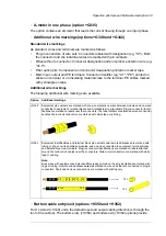
A-meter in one phase
G335
Additional wire markings. See section
Descriptions of options (page 45)
.
G340
G342
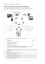
Cabling
Bottom entry. See section
Descriptions of options (page 45)
H350
Top entry. See section
Descriptions of options (page 45)
H351
Bottom exit. See section
Descriptions of options (page 45)
H352
Top exit. See section
Descriptions of options (page 45)
H353
Cable conduit entry (US/UK). See section
Descriptions of options (page 45)
.
H358
Common motor terminal cubicle. See section
Descriptions of options (page 45)
H359
Common output terminals (for inverter modules mounted in the same cubicle). See section
H366
Fieldbus adapters
FDNA-01 DeviceNet™ adapter module
K451
FPBA-01 PROFIBUS DP adapter module
K454
FCAN-01 CANopen adapter module
K457
FSCA-01 RS-485 (Modbus/RTU) adapter module
K458
FCNA-01 ControlNet™ adapter module
K462
FECA-01 EtherCat adapter module
K469
FEPL-02 EtherPOWERLINK adapter module
K470
FENA-11 Ethernet adapter module for EtherNet/IP™, Modbus TCP and PROFINET IO protocols
K473
FENA-21 Ethernet adapter module for EtherNet/IP™, Modbus TCP and PROFINET IO protocols,
2-port
K475
I/O extensions and feedback interfaces
FIO-11 analog I/O extension module
L500
FIO-01 digital I/O extension module
L501
FEN-31 HTL incremental encoder interface module
L502
FDCO-01 optical DDCS communication adapter module
L503
Additional I/O terminal block. See section
Descriptions of options (page 45)
L504
Thermal protection with PTC relays (1 or 2 pcs). See section
Descriptions of options (page 45)
L505
Thermal protection with Pt100 relays (2, 3, 5 or 8 pcs). See section
Descriptions of options (page 45)
.
L506
FDCO-02 optical DDCS communication adapter module
L508
ATEX-certified thermal protection with PTC relays (1 or 2 pcs)
L513
ATEX-certified thermal protection with Pt100 relays (3, 5 or 8 pcs)
L514
FEA-03 I/O extension adapter
L515
FEN-21 resolver interface module
L516
FEN-01 TTL incremental encoder interface module
L517
56 Operation principle and hardware description
Summary of Contents for ACS880-07
Page 1: ...ABB industrial drives Hardware manual ACS880 07 drives 560 to 2800 kW ...
Page 2: ......
Page 4: ......
Page 22: ...22 ...
Page 28: ...28 ...
Page 94: ...94 ...
Page 112: ...Electrical installation 109 5 6 4 3 112 Electrical installation ...
Page 113: ...110 Electrical installation 7 8 8 Electrical installation 113 ...
Page 114: ...Electrical installation 111 9 10 114 Electrical installation ...
Page 116: ...Electrical installation 113 4 5 3 6 7 116 Electrical installation ...
Page 118: ...2 11 b PE 10 7 5 6 8 a 360 grounding detail 118 Electrical installation ...
Page 128: ...128 ...
Page 146: ...146 ...
Page 148: ...148 ...
Page 159: ...12 Install and tighten the two M4 12 T20 screws 10 11 12 Maintenance 159 ...
Page 162: ...6 6a 6a 6b 7a 7b 7 8 8a 8b 162 Maintenance ...
Page 166: ...166 Maintenance 6 6 7 8 7 166 Maintenance ...
Page 173: ...6 Reinstall the cover removed earlier and close the cubicle door 4 4 D7T D8T Maintenance 173 ...
Page 213: ... Dimension drawing examples Frame 2 D7T 2 R8i 12 pulse A004 Dimensions 213 ...
Page 214: ...Frame 1 D8T 2 R8i IP22 214 Dimensions ...
Page 215: ...Frame 1 D8T 2 R8i IP54 B055 Dimensions 215 ...
Page 216: ...Frame 1 D8T 2 R8i with common motor terminal cubicle H359 1 2 216 Dimensions ...
Page 217: ...Frame 1 D8T 2 R8i with common motor terminal cubicle H359 2 2 Dimensions 217 ...
Page 218: ...Frame 1 D8T 2 R8i with brake choppers and resistors D150 D151 1 2 218 Dimensions ...
Page 219: ...Frame 1 D8T 2 R8i with brake choppers and resistors D150 D151 2 2 Dimensions 219 ...
Page 220: ...Frame 1 D8T 2 R8i with sine output filter E206 1 2 220 Dimensions ...
Page 221: ...Frame 1 D8T 2 R8i with sine output filter E206 2 2 Dimensions 221 ...
Page 222: ...Frame 2 D8T 2 R8i 12 pulse A004 with grounding switch F259 222 Dimensions ...
Page 223: ...Frame 2 D8T 3 R8i 1 2 Dimensions 223 ...
Page 224: ...Frame 2 D8T 3 R8i 2 2 224 Dimensions ...
Page 225: ...Frame 2 D8T 3 R8i with common motor terminal cubicle H359 1 2 Dimensions 225 ...
Page 226: ...Frame 2 D8T 3 R8i with common motor terminal cubicle H359 2 2 226 Dimensions ...
Page 227: ...Frame 2 D8T 3 R8i with top entry top exit H351 H353 1 2 Dimensions 227 ...
Page 228: ...Frame 2 D8T 3 R8i with top entry top exit 2 2 228 Dimensions ...
Page 229: ...Frame 3 D8T 4 R8i 1 2 Dimensions 229 ...
Page 230: ...Frame 3 D8T 4 R8i 2 2 230 Dimensions ...
Page 231: ...Frame 3 D8T 4 R8i with common motor terminal cubicle H359 1 2 Dimensions 231 ...
Page 232: ...Frame 3 D8T 4 R8i with common motor terminal cubicle H359 2 2 232 Dimensions ...
Page 233: ...Frame 3 D8T 4 R8i with top entry top exit H351 H353 1 2 Dimensions 233 ...
Page 234: ...Frame 3 D8T 4 R8i with top entry top exit H351 H353 2 2 234 Dimensions ...
Page 235: ...Frame 4 D8T 5 R8i 6 pulse with top entry exit UL Listed C129 1 2 Dimensions 235 ...
Page 236: ...Frame 4 D8T 5 R8i 6 pulse with top entry exit UL Listed C129 2 2 236 Dimensions ...
Page 237: ... Dimensions of empty cubicles options C199 C200 C201 IP22 IP42 Dimensions 237 ...
Page 238: ...IP54 238 Dimensions ...
Page 243: ... 1000 mm UL CSA top cable entry Dimensions 243 ...
Page 244: ... 1000 mm UL CSA bottom cable entry 244 Dimensions ...
Page 264: ...264 ...
Page 272: ... 272 ...


