


98 Electrical installation
Note 1
: Keep the shields continuous as close to the connection terminals as possible.
Secure the cables mechanically at the lead-through strain relief.
Note 2:
If the outer surface of the shield is non-conductive:
•
Cut the shield at the midpoint of the bare part. Be careful not to cut the conductors or
the grounding wire (if present).
•
Turn the shield inside out to expose its conductive surface.
•
Cover the turned shield and the stripped cable with copper foil to keep the shielding
continuous.
Note for top entry of cables:
When each cable has its own rubber grommet, sufficient IP
and EMC protection can be achieved. However, if very many control cables come to one
cabinet, plan the installation beforehand as follows:
1.
Make a list of the cables coming to the cabinet.
2.
Sort the cables going to the left into one group and the cables going to the right into
another group to avoid unnecessary crossing of cables inside the cabinet.
3.
Sort the cables in each group according to size.
4.
Group the cables for each grommet as follows ensuring that each cable has a proper
contact to the cushions on both sides.
Cable diameter in mm
Max. number of cables per grommet
< 13
4
< 17
3
< 25
2
> 25
1
A
Stripped cable
B
Conductive surface of the shield exposed
C
Stripped part covered with copper foil
1
Cable shield
2
Copper foil
3
Shielded twisted pair
4
Grounding wire
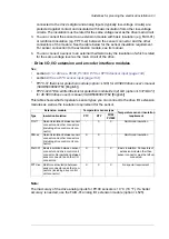
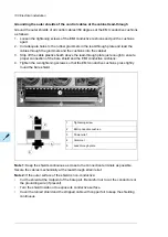
1
A
B
C
2
2
3
4
Stripped cable
A
Conductive surface of the shield exposed
B
Stripped part covered with copper foil
C
Cable shield
1
Copper foil
2
Shielded twisted pair
3
Grounding wire
4
Note for top entry of cables:
When each cable has its own rubber grommet, sufficient IP
and EMC protection can be achieved. However, if very many control cables come to one
cabinet, plan the installation beforehand as follows:
1.
Make a list of the cables coming to the cabinet.
2.
Sort the cables going to the left into one group and the cables going to the right into
another group to avoid unnecessary crossing of cables inside the cabinet.
3.
Sort the cables in each group according to size.
4.
Group the cables for each grommet as follows ensuring that each cable has a proper
contact to the cushions on both sides.
Max. number of cables per grommet
Cable diameter in mm
4
≤ 13
3
≤ 17
2
< 25
1
≥ 25
5.
Arrange the bunches according to size from thickest to the thinnest between the EMI
conductive cushions.
Electrical installation 99
5.
Arrange the bunches according to size from thickest to the thinnest between the EMI
conductive cushions.
6.
If more than one cable go through a grommet, seal the grommet by applying Loctite
5221 (catalogue number 25551) inside the grommet.
Routing the control cables inside the cabinet
Use the existing trunking in the cabinet wherever possible. Use sleeving if cables are laid
against sharp edges. When running cables to or from the swing-out frame, leave enough
slack at the hinge to allow the frame to open fully.
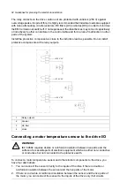
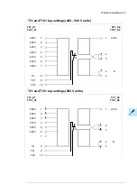
Connecting to the inverter control unit (A41)
Connect the conductors to the appropriate terminals (see page
127
) of the control unit or
terminal block X504 (L504).
Connect the inner twisted pair shields and all separate grounding wires to the grounding
clamps below the control unit.
The drawing below represents a drive with additional I/O terminal block (L504).
Without the block, the grounding is made the same way.
Notes:
•
Do not ground the outer shield of the cable here since it is grounded at the lead-
through.
•
Keep any signal wire pairs twisted as close to the terminals as possible. Twisting the
wire with its return wire reduces disturbances caused by inductive coupling.
6.
If more than one cable go through a grommet, seal the grommet by applying Loctite
5221 (catalogue number 25551) inside the grommet.
Electrical installation 101
Summary of Contents for ACS880-07
Page 1: ...ABB industrial drives Hardware manual ACS880 07 drives 560 to 2800 kW ...
Page 2: ......
Page 4: ......
Page 22: ...22 ...
Page 28: ...28 ...
Page 94: ...94 ...
Page 112: ...Electrical installation 109 5 6 4 3 112 Electrical installation ...
Page 113: ...110 Electrical installation 7 8 8 Electrical installation 113 ...
Page 114: ...Electrical installation 111 9 10 114 Electrical installation ...
Page 116: ...Electrical installation 113 4 5 3 6 7 116 Electrical installation ...
Page 118: ...2 11 b PE 10 7 5 6 8 a 360 grounding detail 118 Electrical installation ...
Page 128: ...128 ...
Page 146: ...146 ...
Page 148: ...148 ...
Page 159: ...12 Install and tighten the two M4 12 T20 screws 10 11 12 Maintenance 159 ...
Page 162: ...6 6a 6a 6b 7a 7b 7 8 8a 8b 162 Maintenance ...
Page 166: ...166 Maintenance 6 6 7 8 7 166 Maintenance ...
Page 173: ...6 Reinstall the cover removed earlier and close the cubicle door 4 4 D7T D8T Maintenance 173 ...
Page 213: ... Dimension drawing examples Frame 2 D7T 2 R8i 12 pulse A004 Dimensions 213 ...
Page 214: ...Frame 1 D8T 2 R8i IP22 214 Dimensions ...
Page 215: ...Frame 1 D8T 2 R8i IP54 B055 Dimensions 215 ...
Page 216: ...Frame 1 D8T 2 R8i with common motor terminal cubicle H359 1 2 216 Dimensions ...
Page 217: ...Frame 1 D8T 2 R8i with common motor terminal cubicle H359 2 2 Dimensions 217 ...
Page 218: ...Frame 1 D8T 2 R8i with brake choppers and resistors D150 D151 1 2 218 Dimensions ...
Page 219: ...Frame 1 D8T 2 R8i with brake choppers and resistors D150 D151 2 2 Dimensions 219 ...
Page 220: ...Frame 1 D8T 2 R8i with sine output filter E206 1 2 220 Dimensions ...
Page 221: ...Frame 1 D8T 2 R8i with sine output filter E206 2 2 Dimensions 221 ...
Page 222: ...Frame 2 D8T 2 R8i 12 pulse A004 with grounding switch F259 222 Dimensions ...
Page 223: ...Frame 2 D8T 3 R8i 1 2 Dimensions 223 ...
Page 224: ...Frame 2 D8T 3 R8i 2 2 224 Dimensions ...
Page 225: ...Frame 2 D8T 3 R8i with common motor terminal cubicle H359 1 2 Dimensions 225 ...
Page 226: ...Frame 2 D8T 3 R8i with common motor terminal cubicle H359 2 2 226 Dimensions ...
Page 227: ...Frame 2 D8T 3 R8i with top entry top exit H351 H353 1 2 Dimensions 227 ...
Page 228: ...Frame 2 D8T 3 R8i with top entry top exit 2 2 228 Dimensions ...
Page 229: ...Frame 3 D8T 4 R8i 1 2 Dimensions 229 ...
Page 230: ...Frame 3 D8T 4 R8i 2 2 230 Dimensions ...
Page 231: ...Frame 3 D8T 4 R8i with common motor terminal cubicle H359 1 2 Dimensions 231 ...
Page 232: ...Frame 3 D8T 4 R8i with common motor terminal cubicle H359 2 2 232 Dimensions ...
Page 233: ...Frame 3 D8T 4 R8i with top entry top exit H351 H353 1 2 Dimensions 233 ...
Page 234: ...Frame 3 D8T 4 R8i with top entry top exit H351 H353 2 2 234 Dimensions ...
Page 235: ...Frame 4 D8T 5 R8i 6 pulse with top entry exit UL Listed C129 1 2 Dimensions 235 ...
Page 236: ...Frame 4 D8T 5 R8i 6 pulse with top entry exit UL Listed C129 2 2 236 Dimensions ...
Page 237: ... Dimensions of empty cubicles options C199 C200 C201 IP22 IP42 Dimensions 237 ...
Page 238: ...IP54 238 Dimensions ...
Page 243: ... 1000 mm UL CSA top cable entry Dimensions 243 ...
Page 244: ... 1000 mm UL CSA bottom cable entry 244 Dimensions ...
Page 264: ...264 ...
Page 272: ... 272 ...


