


Connector pitch 5 mm, wire size 2.5 mm
2
Digital inputs DI1…DI6 (XDI:1…XDI:6)
24 V logic levels: “0” < 5 V, “1” > 15 V
R
in
: 2.0 kohm
Input type: NPN/PNP (DI1…DI5), NPN (DI6)
Hardware filtering: 0.04 ms, digital filtering up to 8 ms
DI6 (XDI:6) can alternatively be used as an input for a PTC sensor.
“0” > 4 kohm, “1” < 1.5 kohm.
I
max
: 15 mA (DI1…DI5), 5 mA (DI6)
Connector pitch 5 mm, wire size 2.5 mm
2
Start interlock input DIIL (XDI:7)
24 V logic levels: “0” < 5 V, “1” > 15 V
R
in
: 2.0 kohm
Input type: NPN/PNP
Hardware filtering: 0.04 ms, digital filtering up to 8 ms
Connector pitch 5 mm, wire size 2.5 mm
2
Digital inputs/outputs DIO1 and DIO2
(XDIO:1 and XDIO:2)
As inputs: 24 V logic levels: “0” < 5 V, “1” > 15 V.
R
in
: 2.0 kohm. Fil-
tering: 1 ms.
Input/output mode selection by paramet-
ers.
As outputs: Total output current from +24VD is limited to 200 mA
DIO1 can be configured as a frequency
input (0…16 kHz with hardware filtering
of 4 microseconds) for 24 V level square
wave signal (sinusoidal or other wave
form cannot be used). DIO2 can be con-
figured as a 24 V level square wave fre-
quency output. See the firmware manual
of the supply/inverter unit, parameter
group 111/11.
Control units of the drive 135
Control unit connector data
Power supply
(XPOW)
Connector pitch 5 mm, wire size 2.5 mm
2
24 V (±10%) DC, 2 A
External power input. Two supplies can be connected for
redundancy.
Relay outputs RO1…RO3
(XRO1…XRO3)
Connector pitch 5 mm, wire size 2.5 mm
2
250 V AC / 30 V DC, 2 A
Protected by varistors
+24 V output
(XD24:2 and XD24:4)
Connector pitch 5 mm, wire size 2.5 mm
2
Total load capacity of these outputs is 4.8 W (200 mA / 24 V) minus
the power taken by DIO1 and DIO2.
Digital inputs DI1…DI6
(XDI:1…XDI:6)
Connector pitch 5 mm, wire size 2.5 mm
2
24 V logic levels: “0” < 5 V, “1” > 15 V
R
in
: 2.0 kohm
Input type: NPN/PNP (DI1…DI5), NPN (DI6)
Hardware filtering: 0.04 ms, digital filtering up to 8 ms
DI6 (XDI:6) can alternatively be used as an input for a PTC sensor.
“0” > 4 kohm, “1” < 1.5 kohm
I
max
: 15 mA (DI1…DI5), 5 mA (DI6)
Start interlock input DIIL
(XDI:7)
Connector pitch 5 mm, wire size 2.5 mm
2
24 V logic levels: “0” < 5 V, “1” > 15 V
R
in
: 2.0 kohm
Input type: NPN/PNP
Hardware filtering: 0.04 ms, digital filtering up to 8 ms
Digital inputs/outputs DIO1 and DIO2
(XDIO:1 and XDIO:2)
Input/output mode selection by
parameters.
DIO1 can be configured as a frequency
input (0…16 kHz with hardware filtering
of 4 microseconds) for 24 V level square
wave signal (sinusoidal or other wave
form cannot be used). DIO2 can be
configured as a 24 V level square wave
frequency output. See the firmware
manual of the supply/inverter unit,
parameter group 111/11.
Connector pitch 5 mm, wire size 2.5 mm
2
As inputs:
24 V logic levels: “0” < 5 V, “1” > 15 V
R
in
: 2.0 kohm
Filtering: 1 ms
As outputs:
Total output current from +24VD is limited to 200 mA
Reference voltage for analog inputs
+VREF and -VREF
(XAI:1 and XAI:2)
Connector pitch 5 mm, wire size 2.5 mm
2
10 V ±1% and –10 V ±1%,
R
load
1…10 kohm
Maximum output current: 10 mA
Analog inputs AI1 and AI2
(XAI:4 … XAI:7).
Current/voltage input mode selection by
switches.
Connector pitch 5 mm, wire size 2.5 mm
2
Current input: –20…20 mA,
R
in
= 100 ohm
Voltage input: –10…10 V,
R
in
> 200 kohm
Differential inputs, common mode range ±30 V
Sampling interval per channel: 0.25 ms
Hardware filtering: 0.25 ms, adjustable digital filtering up to 8 ms
Resolution: 11 bit + sign bit
Inaccuracy: 1% of full scale range
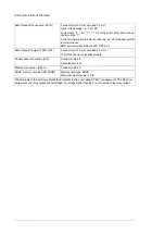
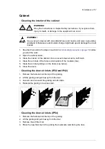
R
L
DIOx
DIOGND
+24VD
Connector pitch 5 mm, wire size 2.5 mm
2
Reference voltage for analog inputs
+VREF and -VREF (XAI:1 and XAI:2)
10 V ±1% and –10 V ±1%,
R
load
1…10 kohm
Maximum output current: 10 mA
Connector pitch 5 mm, wire size 2.5 mm
2
Analog inputs AI1 and AI2
(XAI:4 … XAI:7).
Current input: –20…20 mA,
R
in
= 100 ohm
Current/voltage input mode selection by
switches.
Voltage input: –10…10 V,
R
in
> 200 kohm
Differential inputs, common mode range ±30 V
Sampling interval per channel: 0.25 ms
Hardware filtering: 0.25 ms, adjustable digital filtering up to 8 ms
Resolution: 11 bit + sign bit
Inaccuracy: 1% of full scale range
Connector pitch 5 mm, wire size 2.5 mm
2
Analog outputs AO1 and AO2 (XAO)
0…20 mA,
R
load
< 500 ohm
Frequency range: 0…500 Hz
Resolution: 11 bit + sign bit
Inaccuracy: 2% of full scale range
Connector pitch 5 mm, wire size 2.5 mm
2
Drive-to-drive link (XD2D)
Physical layer: RS-485
Termination by jumper or switch
Connector pitch 5 mm, wire size 2.5 mm
2
RS-485 connection (X485)
Physical layer: RS-485
Control units of the drive 137
Summary of Contents for ACS880-07
Page 1: ...ABB industrial drives Hardware manual ACS880 07 drives 560 to 2800 kW ...
Page 2: ......
Page 4: ......
Page 22: ...22 ...
Page 28: ...28 ...
Page 94: ...94 ...
Page 112: ...Electrical installation 109 5 6 4 3 112 Electrical installation ...
Page 113: ...110 Electrical installation 7 8 8 Electrical installation 113 ...
Page 114: ...Electrical installation 111 9 10 114 Electrical installation ...
Page 116: ...Electrical installation 113 4 5 3 6 7 116 Electrical installation ...
Page 118: ...2 11 b PE 10 7 5 6 8 a 360 grounding detail 118 Electrical installation ...
Page 128: ...128 ...
Page 146: ...146 ...
Page 148: ...148 ...
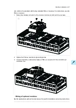
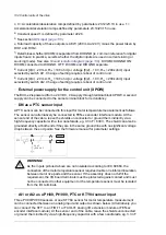
Page 159: ...12 Install and tighten the two M4 12 T20 screws 10 11 12 Maintenance 159 ...
Page 162: ...6 6a 6a 6b 7a 7b 7 8 8a 8b 162 Maintenance ...
Page 166: ...166 Maintenance 6 6 7 8 7 166 Maintenance ...
Page 173: ...6 Reinstall the cover removed earlier and close the cubicle door 4 4 D7T D8T Maintenance 173 ...
Page 213: ... Dimension drawing examples Frame 2 D7T 2 R8i 12 pulse A004 Dimensions 213 ...
Page 214: ...Frame 1 D8T 2 R8i IP22 214 Dimensions ...
Page 215: ...Frame 1 D8T 2 R8i IP54 B055 Dimensions 215 ...
Page 216: ...Frame 1 D8T 2 R8i with common motor terminal cubicle H359 1 2 216 Dimensions ...
Page 217: ...Frame 1 D8T 2 R8i with common motor terminal cubicle H359 2 2 Dimensions 217 ...
Page 218: ...Frame 1 D8T 2 R8i with brake choppers and resistors D150 D151 1 2 218 Dimensions ...
Page 219: ...Frame 1 D8T 2 R8i with brake choppers and resistors D150 D151 2 2 Dimensions 219 ...
Page 220: ...Frame 1 D8T 2 R8i with sine output filter E206 1 2 220 Dimensions ...
Page 221: ...Frame 1 D8T 2 R8i with sine output filter E206 2 2 Dimensions 221 ...
Page 222: ...Frame 2 D8T 2 R8i 12 pulse A004 with grounding switch F259 222 Dimensions ...
Page 223: ...Frame 2 D8T 3 R8i 1 2 Dimensions 223 ...
Page 224: ...Frame 2 D8T 3 R8i 2 2 224 Dimensions ...
Page 225: ...Frame 2 D8T 3 R8i with common motor terminal cubicle H359 1 2 Dimensions 225 ...
Page 226: ...Frame 2 D8T 3 R8i with common motor terminal cubicle H359 2 2 226 Dimensions ...
Page 227: ...Frame 2 D8T 3 R8i with top entry top exit H351 H353 1 2 Dimensions 227 ...
Page 228: ...Frame 2 D8T 3 R8i with top entry top exit 2 2 228 Dimensions ...
Page 229: ...Frame 3 D8T 4 R8i 1 2 Dimensions 229 ...
Page 230: ...Frame 3 D8T 4 R8i 2 2 230 Dimensions ...
Page 231: ...Frame 3 D8T 4 R8i with common motor terminal cubicle H359 1 2 Dimensions 231 ...
Page 232: ...Frame 3 D8T 4 R8i with common motor terminal cubicle H359 2 2 232 Dimensions ...
Page 233: ...Frame 3 D8T 4 R8i with top entry top exit H351 H353 1 2 Dimensions 233 ...
Page 234: ...Frame 3 D8T 4 R8i with top entry top exit H351 H353 2 2 234 Dimensions ...
Page 235: ...Frame 4 D8T 5 R8i 6 pulse with top entry exit UL Listed C129 1 2 Dimensions 235 ...
Page 236: ...Frame 4 D8T 5 R8i 6 pulse with top entry exit UL Listed C129 2 2 236 Dimensions ...
Page 237: ... Dimensions of empty cubicles options C199 C200 C201 IP22 IP42 Dimensions 237 ...
Page 238: ...IP54 238 Dimensions ...
Page 243: ... 1000 mm UL CSA top cable entry Dimensions 243 ...
Page 244: ... 1000 mm UL CSA bottom cable entry 244 Dimensions ...
Page 264: ...264 ...
Page 272: ... 272 ...


