


■
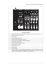
Additional terminal block X504 (L504)
The standard terminal blocks of the drive control unit are wired to the additional terminal
block at the factory for customer control wiring. The terminals are spring loaded.
Cables accepted by the terminals:
•
solid wire 0.08 to 4 mm2
•
stranded wire with ferrule 0.14 to 2.5 mm2
•
stranded wire without ferrule 0.08 to 2.5 mm2 (28 to 12 AWG).
Stripping length: 10 mm.
Note:
The optional modules inserted in the slots of the control unit (or optional FEA-03 extension
adapter) are not wired to the additional terminal block. The customer must connect the
optional module control wires directly to the modules.
■
Thermal protection with PTC relays (oL505, +2L505, +L513,
+2L513, +L536, +L537)
PTC thermistor relay options are used for overtemperature supervision of motors equipped
with PTC sensors. When the motor temperature rises to the thermistor wake-up level, the
resistance of the sensor increases sharply. The relay detects the change and indicates
motor overtemperature through its contacts.
+L505, +2L505, +L513, +2L513
L505 provides a thermistor relay and a terminal block. The terminal block has
connections for the measuring circuit (one to three PTC sensors in series), the output
indication of the relay, and an optional external reset button. The relay can be reset either
locally or externally, or the reset circuit can be jumpered for automatic reset.
The output indication of the relay can be wired by the customer for example to
•
the main contactor or breaker control circuit of the drive, to open it in case of motor
overtemperature,
•
the appropriate digital input of the drive, to trip the drive and generate a fault message
in case of motor overtemperature, or
•
an external monitoring circuit.
L513 is an ATEX-certified thermal protection function that has the same external
connectivity as +L505. In addition, +L513 comes with +Q971 (ATEX-certified safe
disconnection function) as standard and is wired at the factory to activate the Safe torque
off function of the drive in an overtemperature situation. A manual reset for the protection
function is required by Ex/ATEX regulations. For more information, see
ATEX-certified motor
thermal protection functions for cabinet-built ACS880 drives (oL513+Q971 and
+L514+Q971) user's manual
(3AXD50000014979 [English]).
O2L505 and +2L513 duplicate oL505 and +L513 respectively, containing
the relays and connections for two separate measurement circuits.
Operation principle and hardware description 51
Summary of Contents for ACS880-07
Page 1: ...ABB industrial drives Hardware manual ACS880 07 drives 560 to 2800 kW ...
Page 2: ......
Page 4: ......
Page 22: ...22 ...
Page 28: ...28 ...
Page 94: ...94 ...
Page 112: ...Electrical installation 109 5 6 4 3 112 Electrical installation ...
Page 113: ...110 Electrical installation 7 8 8 Electrical installation 113 ...
Page 114: ...Electrical installation 111 9 10 114 Electrical installation ...
Page 116: ...Electrical installation 113 4 5 3 6 7 116 Electrical installation ...
Page 118: ...2 11 b PE 10 7 5 6 8 a 360 grounding detail 118 Electrical installation ...
Page 128: ...128 ...
Page 146: ...146 ...
Page 148: ...148 ...
Page 159: ...12 Install and tighten the two M4 12 T20 screws 10 11 12 Maintenance 159 ...
Page 162: ...6 6a 6a 6b 7a 7b 7 8 8a 8b 162 Maintenance ...
Page 166: ...166 Maintenance 6 6 7 8 7 166 Maintenance ...
Page 173: ...6 Reinstall the cover removed earlier and close the cubicle door 4 4 D7T D8T Maintenance 173 ...
Page 213: ... Dimension drawing examples Frame 2 D7T 2 R8i 12 pulse A004 Dimensions 213 ...
Page 214: ...Frame 1 D8T 2 R8i IP22 214 Dimensions ...
Page 215: ...Frame 1 D8T 2 R8i IP54 B055 Dimensions 215 ...
Page 216: ...Frame 1 D8T 2 R8i with common motor terminal cubicle H359 1 2 216 Dimensions ...
Page 217: ...Frame 1 D8T 2 R8i with common motor terminal cubicle H359 2 2 Dimensions 217 ...
Page 218: ...Frame 1 D8T 2 R8i with brake choppers and resistors D150 D151 1 2 218 Dimensions ...
Page 219: ...Frame 1 D8T 2 R8i with brake choppers and resistors D150 D151 2 2 Dimensions 219 ...
Page 220: ...Frame 1 D8T 2 R8i with sine output filter E206 1 2 220 Dimensions ...
Page 221: ...Frame 1 D8T 2 R8i with sine output filter E206 2 2 Dimensions 221 ...
Page 222: ...Frame 2 D8T 2 R8i 12 pulse A004 with grounding switch F259 222 Dimensions ...
Page 223: ...Frame 2 D8T 3 R8i 1 2 Dimensions 223 ...
Page 224: ...Frame 2 D8T 3 R8i 2 2 224 Dimensions ...
Page 225: ...Frame 2 D8T 3 R8i with common motor terminal cubicle H359 1 2 Dimensions 225 ...
Page 226: ...Frame 2 D8T 3 R8i with common motor terminal cubicle H359 2 2 226 Dimensions ...
Page 227: ...Frame 2 D8T 3 R8i with top entry top exit H351 H353 1 2 Dimensions 227 ...
Page 228: ...Frame 2 D8T 3 R8i with top entry top exit 2 2 228 Dimensions ...
Page 229: ...Frame 3 D8T 4 R8i 1 2 Dimensions 229 ...
Page 230: ...Frame 3 D8T 4 R8i 2 2 230 Dimensions ...
Page 231: ...Frame 3 D8T 4 R8i with common motor terminal cubicle H359 1 2 Dimensions 231 ...
Page 232: ...Frame 3 D8T 4 R8i with common motor terminal cubicle H359 2 2 232 Dimensions ...
Page 233: ...Frame 3 D8T 4 R8i with top entry top exit H351 H353 1 2 Dimensions 233 ...
Page 234: ...Frame 3 D8T 4 R8i with top entry top exit H351 H353 2 2 234 Dimensions ...
Page 235: ...Frame 4 D8T 5 R8i 6 pulse with top entry exit UL Listed C129 1 2 Dimensions 235 ...
Page 236: ...Frame 4 D8T 5 R8i 6 pulse with top entry exit UL Listed C129 2 2 236 Dimensions ...
Page 237: ... Dimensions of empty cubicles options C199 C200 C201 IP22 IP42 Dimensions 237 ...
Page 238: ...IP54 238 Dimensions ...
Page 243: ... 1000 mm UL CSA top cable entry Dimensions 243 ...
Page 244: ... 1000 mm UL CSA bottom cable entry 244 Dimensions ...
Page 264: ...264 ...
Page 272: ... 272 ...


