


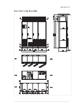

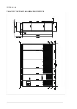


2×D8T + 2×R8i – 12-pulse connection (A004), with grounding switch (F259)
Line-up
width
Shipping
split
widths
Brake
resistor
3
1)
Brake
chopper
3
1)
Brake
resistor
2
1)
Brake
chopper
2
1)
Brake
resistor
1
1)
Brake
chopper
1
1)
Joining
cubicle
Common
motor
terminal
cubicle
Inverter
module
cubicle
Incoming
cubicle
(ICU)
2
Supply
module
cubicle
Incoming
cubicle
(ICU)
1
Auxiliary
control
cubicle
(ACU)
2400
2400
600
400
600
400
400
2700
2700
300
600
400
600
400
400
3600
3600
400
400
400
600
400
600
400
400
6200
2600 + 3600
800
400
800
400
800
400
200
600
400
600
400
400
3900
3900
400
400
400
300
600
400
600
400
400
6300
2700 + 3600
800
400
800
400
800
400
300
600
400
600
400
400
1)
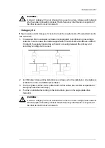
The number of brake choppers depends on required braking power. See chapter
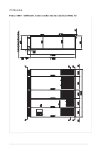
2×D8T + 3×R8i – 6-pulse connection; 12-pulse connection (A004) without grounding switch (no
F259)
Line-up
width
Common
motor termin-
al cubicle
Inverter
module cu-
bicle
Supply mod-
ule cubicle
Adapter for
top cable
entry
Incoming cu-
bicle (ICU)
Auxiliary
control cu-
bicle (ACU)
Supply
voltage
range (V)
2400
800
600
600
400
500/690
2600
800
600
200
600
400
500/690
2800
400
800
600
600
400
500
2700
300
800
600
600
400
690
3000
400
800
600
200
600
400
500
2900
300
800
600
200
600
400
690
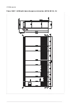
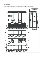
2×D8T + 3×R8i – 12-pulse connection (A004), with grounding switch (F259)
Line-up
width
Common
motor termin-
al cubicle
Inverter
module cu-
bicle
Incoming cu-
bicle (ICU) 2
Supply mod-
ule cubicle
Incoming cu-
bicle (ICU) 1
Auxiliary
control cu-
bicle (ACU)
Supply
voltage
range (V)
2400
800
400
600
400
400
500/690
3000
400
800
400
600
400
400
500
2900
300
800
400
600
400
400
690
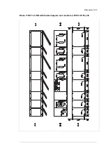
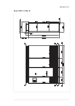
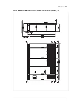
3×D8T + 3×R8i
Line-up width
Common mo-
tor terminal
cubicle
1)
Inverter mod-
ule cubicle
Supply module
cubicle
Adapter for top
cable entry
Incoming cu-
bicle (ICU)
Auxiliary con-
trol cubicle
(ACU)
2600
800
800
600
400
2800
800
800
200
600
400
3000
400
800
800
600
400
3200
400
800
800
200
600
400
3400
600
800
800
200
600
400
1)
600 mm with ACS880-07-2610-3 with top cable exit, otherwise 400 mm.
210 Dimensions
Summary of Contents for ACS880-07
Page 1: ...ABB industrial drives Hardware manual ACS880 07 drives 560 to 2800 kW ...
Page 2: ......
Page 4: ......
Page 22: ...22 ...
Page 28: ...28 ...
Page 94: ...94 ...
Page 112: ...Electrical installation 109 5 6 4 3 112 Electrical installation ...
Page 113: ...110 Electrical installation 7 8 8 Electrical installation 113 ...
Page 114: ...Electrical installation 111 9 10 114 Electrical installation ...
Page 116: ...Electrical installation 113 4 5 3 6 7 116 Electrical installation ...
Page 118: ...2 11 b PE 10 7 5 6 8 a 360 grounding detail 118 Electrical installation ...
Page 128: ...128 ...
Page 146: ...146 ...
Page 148: ...148 ...
Page 159: ...12 Install and tighten the two M4 12 T20 screws 10 11 12 Maintenance 159 ...
Page 162: ...6 6a 6a 6b 7a 7b 7 8 8a 8b 162 Maintenance ...
Page 166: ...166 Maintenance 6 6 7 8 7 166 Maintenance ...
Page 173: ...6 Reinstall the cover removed earlier and close the cubicle door 4 4 D7T D8T Maintenance 173 ...
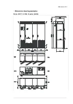
Page 213: ... Dimension drawing examples Frame 2 D7T 2 R8i 12 pulse A004 Dimensions 213 ...
Page 214: ...Frame 1 D8T 2 R8i IP22 214 Dimensions ...
Page 215: ...Frame 1 D8T 2 R8i IP54 B055 Dimensions 215 ...
Page 216: ...Frame 1 D8T 2 R8i with common motor terminal cubicle H359 1 2 216 Dimensions ...
Page 217: ...Frame 1 D8T 2 R8i with common motor terminal cubicle H359 2 2 Dimensions 217 ...
Page 218: ...Frame 1 D8T 2 R8i with brake choppers and resistors D150 D151 1 2 218 Dimensions ...
Page 219: ...Frame 1 D8T 2 R8i with brake choppers and resistors D150 D151 2 2 Dimensions 219 ...
Page 220: ...Frame 1 D8T 2 R8i with sine output filter E206 1 2 220 Dimensions ...
Page 221: ...Frame 1 D8T 2 R8i with sine output filter E206 2 2 Dimensions 221 ...
Page 222: ...Frame 2 D8T 2 R8i 12 pulse A004 with grounding switch F259 222 Dimensions ...
Page 223: ...Frame 2 D8T 3 R8i 1 2 Dimensions 223 ...
Page 224: ...Frame 2 D8T 3 R8i 2 2 224 Dimensions ...
Page 225: ...Frame 2 D8T 3 R8i with common motor terminal cubicle H359 1 2 Dimensions 225 ...
Page 226: ...Frame 2 D8T 3 R8i with common motor terminal cubicle H359 2 2 226 Dimensions ...
Page 227: ...Frame 2 D8T 3 R8i with top entry top exit H351 H353 1 2 Dimensions 227 ...
Page 228: ...Frame 2 D8T 3 R8i with top entry top exit 2 2 228 Dimensions ...
Page 229: ...Frame 3 D8T 4 R8i 1 2 Dimensions 229 ...
Page 230: ...Frame 3 D8T 4 R8i 2 2 230 Dimensions ...
Page 231: ...Frame 3 D8T 4 R8i with common motor terminal cubicle H359 1 2 Dimensions 231 ...
Page 232: ...Frame 3 D8T 4 R8i with common motor terminal cubicle H359 2 2 232 Dimensions ...
Page 233: ...Frame 3 D8T 4 R8i with top entry top exit H351 H353 1 2 Dimensions 233 ...
Page 234: ...Frame 3 D8T 4 R8i with top entry top exit H351 H353 2 2 234 Dimensions ...
Page 235: ...Frame 4 D8T 5 R8i 6 pulse with top entry exit UL Listed C129 1 2 Dimensions 235 ...
Page 236: ...Frame 4 D8T 5 R8i 6 pulse with top entry exit UL Listed C129 2 2 236 Dimensions ...
Page 237: ... Dimensions of empty cubicles options C199 C200 C201 IP22 IP42 Dimensions 237 ...
Page 238: ...IP54 238 Dimensions ...
Page 243: ... 1000 mm UL CSA top cable entry Dimensions 243 ...
Page 244: ... 1000 mm UL CSA bottom cable entry 244 Dimensions ...
Page 264: ...264 ...
Page 272: ... 272 ...


