


•
At the chopper end of the cable, connect the R+ and R- conductors of the resistor cable
together. Measure the insulation resistance between the combined conductors and the
PE conductor by using a measuring voltage of 1 kV DC. The insulation resistance must
be higher than 1 Mohm.
268 Resistor braking
Connection procedure
WARNING!
Obey the instructions in chapter
Safety instructions
. If you
ignore them, injury or death, or damage to the equipment can occur.
•
Do the steps in section
Precautions before electrical work
on page
19
before you start
the work.
•
Connect the resistor cable at the resistor end only. If a shielded three-conductor cable
is used, cut off the third conductor. Ground the twisted shield of the cable as well as
any separate PE conductor (if present).
•
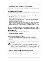
At the chopper end of the cable, connect the R+ and R- conductors of the resistor
cable together. Measure the insulation resistance between the combined conductors
and the PE conductor by using a measuring voltage of 1 kV DC. The insulation
resistance must be higher than 1 Mohm.
•
Connect the resistor cable to the R+ and R- terminals of the chopper. If a shielded
three-conductor cable is used, cut off the third conductor. Ground the twisted shield of
the cable as well as any separate PE conductor (if present).
•
Connect the thermal switch of the brake resistor to the enable input (X1) on the brake
chopper control board. Use cable specified under
Thermal protection of the resistors
(page
267
). If there are multiple thermal switches, connect them in series.
WARNING!
The ENABLE input terminal block of the brake chopper is at
intermediate circuit potential when the supply unit of the drive is running. This
voltage is extremely dangerous and can cause serious damage or injury if the
isolation level and protection conditions for the thermal switches are not sufficient. The
thermal switches must always be properly insulated (over 2.5 kV) and shrouded against
contact.
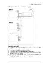
Start-up
Check the settings of the following inverter control program parameters (ACS880 primary
control program):
•
30.30 Overvoltage control
: Overvoltage control disabled.
For settings of other control programs, see the appropriate firmware manual.
Note:
New brake resistors may be coated with storage grease. As the brake chopper
operates for the first time, the grease burns off and may produce some smoke. Make sure
there is proper ventilation.
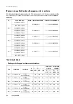
ohm
R-
R+
PE
•
Connect the resistor cable to the R+ and R- terminals of the chopper. If a shielded
three-conductor cable is used, cut off the third conductor. Ground the twisted shield of
the cable as well as any separate PE conductor (if present).
•
Connect the thermal switch of the brake resistor to the enable input (X1) on the brake
chopper control board. Use cable specified under
. If there are multiple thermal switches, connect them in series.
WARNING!
The ENABLE input terminal block of the brake chopper is at intermediate circuit
potential when the supply unit of the drive is running. This voltage is extremely
dangerous and can cause serious damage or injury if the isolation level and
protection conditions for the thermal switches are not sufficient. The thermal
switches must always be properly insulated (over 2.5 kV) and shrouded against
contact.
Brake system start up
Check the settings of the following inverter control program parameters (ACS880 primary
control program):
•
30.30 Overvoltage control
: Overvoltage control disabled.
For settings of other control programs, see the appropriate firmware manual.
Note:
New brake resistors may be coated with storage grease. As the brake chopper operates
for the first time, the grease burns off and may produce some smoke. Make sure there is
proper ventilation.
Resistor braking 271
Summary of Contents for ACS880-07
Page 1: ...ABB industrial drives Hardware manual ACS880 07 drives 560 to 2800 kW ...
Page 2: ......
Page 4: ......
Page 22: ...22 ...
Page 28: ...28 ...
Page 94: ...94 ...
Page 112: ...Electrical installation 109 5 6 4 3 112 Electrical installation ...
Page 113: ...110 Electrical installation 7 8 8 Electrical installation 113 ...
Page 114: ...Electrical installation 111 9 10 114 Electrical installation ...
Page 116: ...Electrical installation 113 4 5 3 6 7 116 Electrical installation ...
Page 118: ...2 11 b PE 10 7 5 6 8 a 360 grounding detail 118 Electrical installation ...
Page 128: ...128 ...
Page 146: ...146 ...
Page 148: ...148 ...
Page 159: ...12 Install and tighten the two M4 12 T20 screws 10 11 12 Maintenance 159 ...
Page 162: ...6 6a 6a 6b 7a 7b 7 8 8a 8b 162 Maintenance ...
Page 166: ...166 Maintenance 6 6 7 8 7 166 Maintenance ...
Page 173: ...6 Reinstall the cover removed earlier and close the cubicle door 4 4 D7T D8T Maintenance 173 ...
Page 213: ... Dimension drawing examples Frame 2 D7T 2 R8i 12 pulse A004 Dimensions 213 ...
Page 214: ...Frame 1 D8T 2 R8i IP22 214 Dimensions ...
Page 215: ...Frame 1 D8T 2 R8i IP54 B055 Dimensions 215 ...
Page 216: ...Frame 1 D8T 2 R8i with common motor terminal cubicle H359 1 2 216 Dimensions ...
Page 217: ...Frame 1 D8T 2 R8i with common motor terminal cubicle H359 2 2 Dimensions 217 ...
Page 218: ...Frame 1 D8T 2 R8i with brake choppers and resistors D150 D151 1 2 218 Dimensions ...
Page 219: ...Frame 1 D8T 2 R8i with brake choppers and resistors D150 D151 2 2 Dimensions 219 ...
Page 220: ...Frame 1 D8T 2 R8i with sine output filter E206 1 2 220 Dimensions ...
Page 221: ...Frame 1 D8T 2 R8i with sine output filter E206 2 2 Dimensions 221 ...
Page 222: ...Frame 2 D8T 2 R8i 12 pulse A004 with grounding switch F259 222 Dimensions ...
Page 223: ...Frame 2 D8T 3 R8i 1 2 Dimensions 223 ...
Page 224: ...Frame 2 D8T 3 R8i 2 2 224 Dimensions ...
Page 225: ...Frame 2 D8T 3 R8i with common motor terminal cubicle H359 1 2 Dimensions 225 ...
Page 226: ...Frame 2 D8T 3 R8i with common motor terminal cubicle H359 2 2 226 Dimensions ...
Page 227: ...Frame 2 D8T 3 R8i with top entry top exit H351 H353 1 2 Dimensions 227 ...
Page 228: ...Frame 2 D8T 3 R8i with top entry top exit 2 2 228 Dimensions ...
Page 229: ...Frame 3 D8T 4 R8i 1 2 Dimensions 229 ...
Page 230: ...Frame 3 D8T 4 R8i 2 2 230 Dimensions ...
Page 231: ...Frame 3 D8T 4 R8i with common motor terminal cubicle H359 1 2 Dimensions 231 ...
Page 232: ...Frame 3 D8T 4 R8i with common motor terminal cubicle H359 2 2 232 Dimensions ...
Page 233: ...Frame 3 D8T 4 R8i with top entry top exit H351 H353 1 2 Dimensions 233 ...
Page 234: ...Frame 3 D8T 4 R8i with top entry top exit H351 H353 2 2 234 Dimensions ...
Page 235: ...Frame 4 D8T 5 R8i 6 pulse with top entry exit UL Listed C129 1 2 Dimensions 235 ...
Page 236: ...Frame 4 D8T 5 R8i 6 pulse with top entry exit UL Listed C129 2 2 236 Dimensions ...
Page 237: ... Dimensions of empty cubicles options C199 C200 C201 IP22 IP42 Dimensions 237 ...
Page 238: ...IP54 238 Dimensions ...
Page 243: ... 1000 mm UL CSA top cable entry Dimensions 243 ...
Page 244: ... 1000 mm UL CSA bottom cable entry 244 Dimensions ...
Page 264: ...264 ...
Page 272: ... 272 ...


