


•
section
Powering the heating and lighting equipment (oG300, +G301 and
•
circuit diagrams delivered with drive for the actual wiring.
■
Cabinet lighting (G301)
This option contains LED lighting fixtures in each cubicle (except joining and brake resistor
cubicles) and a 24 V DC power supply. The lighting is powered from the same external
110…240 V AC power source as the cabinet heater (G300).
■
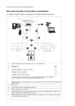
Terminals for external control voltage (G307)
The option provides terminals for connecting external uninterruptible control voltage to the
control unit and control devices when the drive is not powered.
See also sections:
•
Supplying power for the auxiliary circuits (page 91)
•
Connecting a 230/115 V AC auxiliary voltage supply (UPS, G307) (page 104)
•
circuit diagrams delivered with drive for the actual wiring.
■
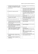
Output for motor space heater (G313)
The option contains:
•
load switch for providing electrical isolation during service
•
miniature circuit breaker for overcurrent protection
•
terminal block for external supply and heating element(s) connection
The heater is off when the drive is running. The customer controls the heating elements in
the motor windings on and off with the external supply. The power and voltage of the motor
heater depend on the motor.
See also sections:
•
Supplying power for the auxiliary circuits (page 91)
•
Powering the heating and lighting equipment (oG300, +G301 and
+G313) (page 107)
•
circuit diagrams delivered with drive for the actual wiring.
■
Supply connection by busbars (G317)
This option provides input (supply) terminals and a busbar entry that enable direct connection
to busbar trunking systems.
■
Ready/Run/Fault lights (oG327…G329)
These options provide "ready" (+G327, white), "run" (+G328, green) and "fault" (+G329,
red) lights installed on the cabinet door.
■
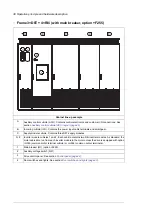
Halogen-free wiring and materials (G330)
The option provides halogen-free cable ducts, control wires and wire sleeves, thus reducing
toxic fire gases.
■
V-meter with selector switch (G334)
The option contains a voltmeter and a selector switch on the cabinet door. The switch selects
the two input phases across which the voltage is measured.
48 Operation principle and hardware description
Summary of Contents for ACS880-07
Page 1: ...ABB industrial drives Hardware manual ACS880 07 drives 560 to 2800 kW ...
Page 2: ......
Page 4: ......
Page 22: ...22 ...
Page 28: ...28 ...
Page 94: ...94 ...
Page 112: ...Electrical installation 109 5 6 4 3 112 Electrical installation ...
Page 113: ...110 Electrical installation 7 8 8 Electrical installation 113 ...
Page 114: ...Electrical installation 111 9 10 114 Electrical installation ...
Page 116: ...Electrical installation 113 4 5 3 6 7 116 Electrical installation ...
Page 118: ...2 11 b PE 10 7 5 6 8 a 360 grounding detail 118 Electrical installation ...
Page 128: ...128 ...
Page 146: ...146 ...
Page 148: ...148 ...
Page 159: ...12 Install and tighten the two M4 12 T20 screws 10 11 12 Maintenance 159 ...
Page 162: ...6 6a 6a 6b 7a 7b 7 8 8a 8b 162 Maintenance ...
Page 166: ...166 Maintenance 6 6 7 8 7 166 Maintenance ...
Page 173: ...6 Reinstall the cover removed earlier and close the cubicle door 4 4 D7T D8T Maintenance 173 ...
Page 213: ... Dimension drawing examples Frame 2 D7T 2 R8i 12 pulse A004 Dimensions 213 ...
Page 214: ...Frame 1 D8T 2 R8i IP22 214 Dimensions ...
Page 215: ...Frame 1 D8T 2 R8i IP54 B055 Dimensions 215 ...
Page 216: ...Frame 1 D8T 2 R8i with common motor terminal cubicle H359 1 2 216 Dimensions ...
Page 217: ...Frame 1 D8T 2 R8i with common motor terminal cubicle H359 2 2 Dimensions 217 ...
Page 218: ...Frame 1 D8T 2 R8i with brake choppers and resistors D150 D151 1 2 218 Dimensions ...
Page 219: ...Frame 1 D8T 2 R8i with brake choppers and resistors D150 D151 2 2 Dimensions 219 ...
Page 220: ...Frame 1 D8T 2 R8i with sine output filter E206 1 2 220 Dimensions ...
Page 221: ...Frame 1 D8T 2 R8i with sine output filter E206 2 2 Dimensions 221 ...
Page 222: ...Frame 2 D8T 2 R8i 12 pulse A004 with grounding switch F259 222 Dimensions ...
Page 223: ...Frame 2 D8T 3 R8i 1 2 Dimensions 223 ...
Page 224: ...Frame 2 D8T 3 R8i 2 2 224 Dimensions ...
Page 225: ...Frame 2 D8T 3 R8i with common motor terminal cubicle H359 1 2 Dimensions 225 ...
Page 226: ...Frame 2 D8T 3 R8i with common motor terminal cubicle H359 2 2 226 Dimensions ...
Page 227: ...Frame 2 D8T 3 R8i with top entry top exit H351 H353 1 2 Dimensions 227 ...
Page 228: ...Frame 2 D8T 3 R8i with top entry top exit 2 2 228 Dimensions ...
Page 229: ...Frame 3 D8T 4 R8i 1 2 Dimensions 229 ...
Page 230: ...Frame 3 D8T 4 R8i 2 2 230 Dimensions ...
Page 231: ...Frame 3 D8T 4 R8i with common motor terminal cubicle H359 1 2 Dimensions 231 ...
Page 232: ...Frame 3 D8T 4 R8i with common motor terminal cubicle H359 2 2 232 Dimensions ...
Page 233: ...Frame 3 D8T 4 R8i with top entry top exit H351 H353 1 2 Dimensions 233 ...
Page 234: ...Frame 3 D8T 4 R8i with top entry top exit H351 H353 2 2 234 Dimensions ...
Page 235: ...Frame 4 D8T 5 R8i 6 pulse with top entry exit UL Listed C129 1 2 Dimensions 235 ...
Page 236: ...Frame 4 D8T 5 R8i 6 pulse with top entry exit UL Listed C129 2 2 236 Dimensions ...
Page 237: ... Dimensions of empty cubicles options C199 C200 C201 IP22 IP42 Dimensions 237 ...
Page 238: ...IP54 238 Dimensions ...
Page 243: ... 1000 mm UL CSA top cable entry Dimensions 243 ...
Page 244: ... 1000 mm UL CSA bottom cable entry 244 Dimensions ...
Page 264: ...264 ...
Page 272: ... 272 ...


