


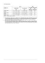


Transportation
in the protective package
Storage
in the protective package
Operation
installed for stationary
use
-
-
0…2000 m (0…6562 ft)
above sea level. For alti-
tudes over 2000 m, contact
ABB.
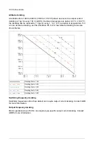
Installation site altitude
Output derated above 1000
m (3281 ft).
-40 to +70 °C (-
40 to +158 °F)
-40 to +70 °C (-
40 to +158 °F)
0 … +40 °C
(+32 … +104 °F). No con-
densation allowed.
Air temperature
Output derated in the
range +40 … +50 °C
(+104 … +122 °F).
Max. 95%
Max. 95%
Max. 95%
Relative humidity
No condensation allowed. Maximum allowed relative humidity is 60% in the presence
of corrosive gases.
IEC 60721-3-2:1997
IEC 60721-3-1:1997
IEC/EN 60721-3-3:2002:
Classification of environ-
mental conditions - Part 3-
3: Classification of groups
of environmental paramet-
ers and their severities -
Stationary use of weather
protected locations
Contamination
Chemical gases: Class
2C2
Solid particles: Class 2S2
Chemical gases: Class
1C2
Solid particles: Class 1S3
(packing must support this,
otherwise 1S2)
Chemical gases: Class
3C2
Solid particles: Class 3S2.
No conductive dust al-
lowed.
IEC/EN 60721-3-2:1997
IEC/EN 60721-3-1:1997
IEC/EN 60721-3-3:2002
Vibration
2…9 Hz: max. 3.5 mm
amplitude
10…57 Hz: max. 0.075 mm
amplitude
10…57 Hz: max. 0.075 mm
amplitude
IEC/EN 61800-5-1
IEC 60068-2-6:2007,
EN 60068-2-6:2008 Envir-
onmental testing Part 2:
Tests –Test Fc: Vibration
(sinusoidal)
9…200 Hz: 10 m/s
2
(32.8 ft/s
2
)
57…150 Hz: 1
g
57…150 Hz: 1
g
Units with marine construc-
tion (C121): Max.
1 mm (0.04 in.)
(5 … 13.2 Hz), max. 0.7
g
(13.2 … 100 Hz) sinusoidal
With packing max.
100 m/s
2
(328 ft/s
2
) 11 ms
With packing max.
100 m/s
2
(328 ft/s
2
) 11 ms
Not allowed
Shock
IEC 60068-2-27:2008, EN
60068-2-27:2009
Environmental testing -
Part 2-27: Tests - Test Ea
and guidance: Shock
Materials
Hot-dip zinc coated 1.5 mm thick steel sheet (thickness of coating approximately
20 micrometers). Polyester thermosetting powder coating (thickness approximately
80 micrometers) on visible surfaces, color RAL 7035 and RAL 9017.
Cabinet
Tin-plated copper
Busbars
Insulating materials and non-metallic items mostly self-extinctive
Fire safety of materials
(IEC 60332-1)
194 Technical data
Summary of Contents for ACS880-07
Page 1: ...ABB industrial drives Hardware manual ACS880 07 drives 560 to 2800 kW ...
Page 2: ......
Page 4: ......
Page 22: ...22 ...
Page 28: ...28 ...
Page 94: ...94 ...
Page 112: ...Electrical installation 109 5 6 4 3 112 Electrical installation ...
Page 113: ...110 Electrical installation 7 8 8 Electrical installation 113 ...
Page 114: ...Electrical installation 111 9 10 114 Electrical installation ...
Page 116: ...Electrical installation 113 4 5 3 6 7 116 Electrical installation ...
Page 118: ...2 11 b PE 10 7 5 6 8 a 360 grounding detail 118 Electrical installation ...
Page 128: ...128 ...
Page 146: ...146 ...
Page 148: ...148 ...
Page 159: ...12 Install and tighten the two M4 12 T20 screws 10 11 12 Maintenance 159 ...
Page 162: ...6 6a 6a 6b 7a 7b 7 8 8a 8b 162 Maintenance ...
Page 166: ...166 Maintenance 6 6 7 8 7 166 Maintenance ...
Page 173: ...6 Reinstall the cover removed earlier and close the cubicle door 4 4 D7T D8T Maintenance 173 ...
Page 213: ... Dimension drawing examples Frame 2 D7T 2 R8i 12 pulse A004 Dimensions 213 ...
Page 214: ...Frame 1 D8T 2 R8i IP22 214 Dimensions ...
Page 215: ...Frame 1 D8T 2 R8i IP54 B055 Dimensions 215 ...
Page 216: ...Frame 1 D8T 2 R8i with common motor terminal cubicle H359 1 2 216 Dimensions ...
Page 217: ...Frame 1 D8T 2 R8i with common motor terminal cubicle H359 2 2 Dimensions 217 ...
Page 218: ...Frame 1 D8T 2 R8i with brake choppers and resistors D150 D151 1 2 218 Dimensions ...
Page 219: ...Frame 1 D8T 2 R8i with brake choppers and resistors D150 D151 2 2 Dimensions 219 ...
Page 220: ...Frame 1 D8T 2 R8i with sine output filter E206 1 2 220 Dimensions ...
Page 221: ...Frame 1 D8T 2 R8i with sine output filter E206 2 2 Dimensions 221 ...
Page 222: ...Frame 2 D8T 2 R8i 12 pulse A004 with grounding switch F259 222 Dimensions ...
Page 223: ...Frame 2 D8T 3 R8i 1 2 Dimensions 223 ...
Page 224: ...Frame 2 D8T 3 R8i 2 2 224 Dimensions ...
Page 225: ...Frame 2 D8T 3 R8i with common motor terminal cubicle H359 1 2 Dimensions 225 ...
Page 226: ...Frame 2 D8T 3 R8i with common motor terminal cubicle H359 2 2 226 Dimensions ...
Page 227: ...Frame 2 D8T 3 R8i with top entry top exit H351 H353 1 2 Dimensions 227 ...
Page 228: ...Frame 2 D8T 3 R8i with top entry top exit 2 2 228 Dimensions ...
Page 229: ...Frame 3 D8T 4 R8i 1 2 Dimensions 229 ...
Page 230: ...Frame 3 D8T 4 R8i 2 2 230 Dimensions ...
Page 231: ...Frame 3 D8T 4 R8i with common motor terminal cubicle H359 1 2 Dimensions 231 ...
Page 232: ...Frame 3 D8T 4 R8i with common motor terminal cubicle H359 2 2 232 Dimensions ...
Page 233: ...Frame 3 D8T 4 R8i with top entry top exit H351 H353 1 2 Dimensions 233 ...
Page 234: ...Frame 3 D8T 4 R8i with top entry top exit H351 H353 2 2 234 Dimensions ...
Page 235: ...Frame 4 D8T 5 R8i 6 pulse with top entry exit UL Listed C129 1 2 Dimensions 235 ...
Page 236: ...Frame 4 D8T 5 R8i 6 pulse with top entry exit UL Listed C129 2 2 236 Dimensions ...
Page 237: ... Dimensions of empty cubicles options C199 C200 C201 IP22 IP42 Dimensions 237 ...
Page 238: ...IP54 238 Dimensions ...
Page 243: ... 1000 mm UL CSA top cable entry Dimensions 243 ...
Page 244: ... 1000 mm UL CSA bottom cable entry 244 Dimensions ...
Page 264: ...264 ...
Page 272: ... 272 ...


