


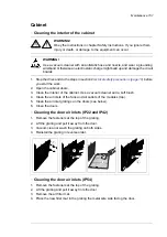


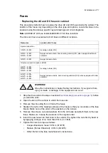


Supply and inverter modules
■
Replacing a frame D7T supply module
WARNING!
Only qualified electricians are allowed to do this work. Read the complete safety
instructions of the drive. Ignoring the instructions can cause physical injury or
death, or damage to the equipment.
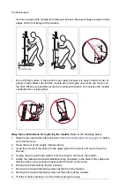
WARNING!
Use extreme caution when maneuvering the supply module. It is heavy and have
a high center of gravity. Ignoring the following instructions can cause physical
injury, or damage to the equipment.
•
Wear appropriate safety equipment.
•
Be careful when removing bolts and washers on top of the module not to drop anything
inside the module.
•
Use a lifting device:
•
Attach the lifting device securely to the module lifting eyes before removing the
module fastening bolts. Keep the lifting device attached to the module until you
have lifted the module onto a pallet and made sure that the module is supported
and cannot topple over.
•
Lift a replacement module only with a lifting device. Keep the lifting device attached
to the module during the work until you are tighten the module fastening bolts.
•
Do not tilt the module. Do not leave the module unattended on a floor.
•
When you push the replacement module into the cabinet, keep your fingers away from
the edge of the module edges to avoid pinching them between the module and the
cabinet.
Obey these instructions for replacing the module.
Refer to the drawings below.
1.
Stop the drive and do the steps in section
Electrical safety precautions (page 19)
before
you start the work.
2.
Open the cubicle door.
3.
Remove the shroud.
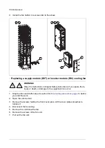
4.
Unplug the plug connector on top of the module (a), and the plug connector and fiber
optic connector in front of the module (b).
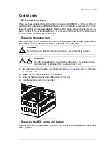
5.
Remove the lower support bracket of the module.
6.
Remove the fastening bolts of the DC busbars (a) and the DC busbars carefully. Do
not drop anything inside the module. Remove the fastening bolts of the AC busbars (b).
7.
Remove the cooling fan plug connector (a) and the cooling fan (b). See also section
about the cooling fan replacement.
8.
Remove the side fastening screws of the module on the top (a) and bottom (b).
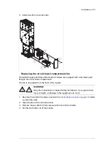
9.
Attach a lifting device to the lifting eyes of the module (a).
10. Remove the upper support brackets of the module (a).
11. Pull the module out of the cabinet carefully. Keep the weight on the lifting device
constantly.
12. Lift the module down onto a pallet.
13. Keep the lifting chain attached to the module and attach the module safely to the pallet.
160 Maintenance
Summary of Contents for ACS880-07
Page 1: ...ABB industrial drives Hardware manual ACS880 07 drives 560 to 2800 kW ...
Page 2: ......
Page 4: ......
Page 22: ...22 ...
Page 28: ...28 ...
Page 94: ...94 ...
Page 112: ...Electrical installation 109 5 6 4 3 112 Electrical installation ...
Page 113: ...110 Electrical installation 7 8 8 Electrical installation 113 ...
Page 114: ...Electrical installation 111 9 10 114 Electrical installation ...
Page 116: ...Electrical installation 113 4 5 3 6 7 116 Electrical installation ...
Page 118: ...2 11 b PE 10 7 5 6 8 a 360 grounding detail 118 Electrical installation ...
Page 128: ...128 ...
Page 146: ...146 ...
Page 148: ...148 ...
Page 159: ...12 Install and tighten the two M4 12 T20 screws 10 11 12 Maintenance 159 ...
Page 162: ...6 6a 6a 6b 7a 7b 7 8 8a 8b 162 Maintenance ...
Page 166: ...166 Maintenance 6 6 7 8 7 166 Maintenance ...
Page 173: ...6 Reinstall the cover removed earlier and close the cubicle door 4 4 D7T D8T Maintenance 173 ...
Page 213: ... Dimension drawing examples Frame 2 D7T 2 R8i 12 pulse A004 Dimensions 213 ...
Page 214: ...Frame 1 D8T 2 R8i IP22 214 Dimensions ...
Page 215: ...Frame 1 D8T 2 R8i IP54 B055 Dimensions 215 ...
Page 216: ...Frame 1 D8T 2 R8i with common motor terminal cubicle H359 1 2 216 Dimensions ...
Page 217: ...Frame 1 D8T 2 R8i with common motor terminal cubicle H359 2 2 Dimensions 217 ...
Page 218: ...Frame 1 D8T 2 R8i with brake choppers and resistors D150 D151 1 2 218 Dimensions ...
Page 219: ...Frame 1 D8T 2 R8i with brake choppers and resistors D150 D151 2 2 Dimensions 219 ...
Page 220: ...Frame 1 D8T 2 R8i with sine output filter E206 1 2 220 Dimensions ...
Page 221: ...Frame 1 D8T 2 R8i with sine output filter E206 2 2 Dimensions 221 ...
Page 222: ...Frame 2 D8T 2 R8i 12 pulse A004 with grounding switch F259 222 Dimensions ...
Page 223: ...Frame 2 D8T 3 R8i 1 2 Dimensions 223 ...
Page 224: ...Frame 2 D8T 3 R8i 2 2 224 Dimensions ...
Page 225: ...Frame 2 D8T 3 R8i with common motor terminal cubicle H359 1 2 Dimensions 225 ...
Page 226: ...Frame 2 D8T 3 R8i with common motor terminal cubicle H359 2 2 226 Dimensions ...
Page 227: ...Frame 2 D8T 3 R8i with top entry top exit H351 H353 1 2 Dimensions 227 ...
Page 228: ...Frame 2 D8T 3 R8i with top entry top exit 2 2 228 Dimensions ...
Page 229: ...Frame 3 D8T 4 R8i 1 2 Dimensions 229 ...
Page 230: ...Frame 3 D8T 4 R8i 2 2 230 Dimensions ...
Page 231: ...Frame 3 D8T 4 R8i with common motor terminal cubicle H359 1 2 Dimensions 231 ...
Page 232: ...Frame 3 D8T 4 R8i with common motor terminal cubicle H359 2 2 232 Dimensions ...
Page 233: ...Frame 3 D8T 4 R8i with top entry top exit H351 H353 1 2 Dimensions 233 ...
Page 234: ...Frame 3 D8T 4 R8i with top entry top exit H351 H353 2 2 234 Dimensions ...
Page 235: ...Frame 4 D8T 5 R8i 6 pulse with top entry exit UL Listed C129 1 2 Dimensions 235 ...
Page 236: ...Frame 4 D8T 5 R8i 6 pulse with top entry exit UL Listed C129 2 2 236 Dimensions ...
Page 237: ... Dimensions of empty cubicles options C199 C200 C201 IP22 IP42 Dimensions 237 ...
Page 238: ...IP54 238 Dimensions ...
Page 243: ... 1000 mm UL CSA top cable entry Dimensions 243 ...
Page 244: ... 1000 mm UL CSA bottom cable entry 244 Dimensions ...
Page 264: ...264 ...
Page 272: ... 272 ...


