


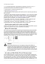


Action
Check that the main switch-disconnector (Q1.1) is switched off, or main breaker (Q1) racked out.
Note:
Some 12-pulse units are equipped with two switch-disconnectors or breakers – check that both are
open before you proceed.
Check that the grounding switch (Q9.1) (F259) is switched on.
12-pulse units have two switches, Q9.1 and Q9.2.
Check the mechanical and electrical installation of the drive. See
Installation checklist (page 141)
.
Check the settings of breakers/switches in the auxiliary circuits. See the circuit diagrams delivered with
the drive.
Check the tap settings of transformers T21, T101 (if present) and T111 (if present). See section
Checking the settings of transformers T21, T101 and T111 (page 96)
Disconnect any unfinished or uninspected auxiliary voltage (115/230 V AC) cables that lead from the
terminal blocks to the outside of the equipment.
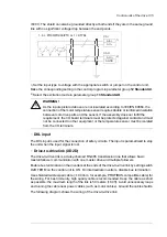
Check that both channels of the Safe torque off circuit connected to the STO inputs of both the supply
control unit [A51] and the inverter control unit [A41] are closed. Refer to the wiring diagrams delivered
with the drive.
If the Safe torque off functionality is used, check that the STO OUT output on the inverter control unit
(A41) is chained to the STO inputs of all inverter modules.
If the Safe torque off functionality is not used, check that the STO input on all inverter modules is correctly
wired to +24 V and ground.
Drives with ground fault monitoring for IT (ungrounded) systems (Q954): Adjust the settings of
the ground fault monitor to suit the installation. See the circuit diagrams of the delivery and
IRDH275B
Ground Fault Monitor Operating Manual
by Bender (code: TGH1386en).
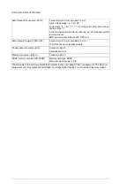
Drives with Pt100 relays ((n)L506):
• Check the connections against the circuit diagrams of the delivery.
• Set the alarm and trip levels of the Pt100 relays.
Set the alarm and trip levels of the Pt100 relay as low as possible based on the operating temperature
and test results of the machine. The trip level can be set, for example, 10 °C higher than what the
temperature of the machine is at maximal load in the maximum environmental temperature.
We recommend to set the operating temperatures of the relay, typically for example, as follows:
• 120…140 °C when only tripping is in use
• alarm 120…140 °C and trip 130…150 °C when both alarm and tripping are used.
Powering up the auxiliary circuit of the drive
Make sure that it is safe to connect voltage. Ensure that
• nobody is working on the drive or circuits that have been wired from outside into the drive cabinet
• the cover of the motor terminal box is in place.
Drives with a voltmeter (G334): Make sure that the circuit breaker of the measuring circuit
(F5.1) is closed.
Close the circuit breakers and/or fuse disconnectors supplying the auxiliary voltage circuits.
Close the cabinet doors.
Close the main breaker of the supply transformer.
Switch on the auxiliary voltage (Q21).
Setting up the supply unit parameters
Check the voltage range setting in parameter
195.01 Supply voltage
.
For more information on setting up the supply control program, see the
ACS880 diode supply control
program firmware manual
(3AUA0000103295 [English]).
If you need more information on the use of the control panel, see the
ACX-AP-x Assistant control
panels user's manual
(3AUA0000085685 [English]).
144 Start-up
Summary of Contents for ACS880-07
Page 1: ...ABB industrial drives Hardware manual ACS880 07 drives 560 to 2800 kW ...
Page 2: ......
Page 4: ......
Page 22: ...22 ...
Page 28: ...28 ...
Page 94: ...94 ...
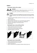
Page 112: ...Electrical installation 109 5 6 4 3 112 Electrical installation ...
Page 113: ...110 Electrical installation 7 8 8 Electrical installation 113 ...
Page 114: ...Electrical installation 111 9 10 114 Electrical installation ...
Page 116: ...Electrical installation 113 4 5 3 6 7 116 Electrical installation ...
Page 118: ...2 11 b PE 10 7 5 6 8 a 360 grounding detail 118 Electrical installation ...
Page 128: ...128 ...
Page 146: ...146 ...
Page 148: ...148 ...
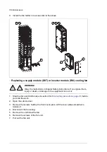
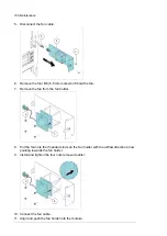
Page 159: ...12 Install and tighten the two M4 12 T20 screws 10 11 12 Maintenance 159 ...
Page 162: ...6 6a 6a 6b 7a 7b 7 8 8a 8b 162 Maintenance ...
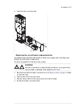
Page 166: ...166 Maintenance 6 6 7 8 7 166 Maintenance ...
Page 173: ...6 Reinstall the cover removed earlier and close the cubicle door 4 4 D7T D8T Maintenance 173 ...
Page 213: ... Dimension drawing examples Frame 2 D7T 2 R8i 12 pulse A004 Dimensions 213 ...
Page 214: ...Frame 1 D8T 2 R8i IP22 214 Dimensions ...
Page 215: ...Frame 1 D8T 2 R8i IP54 B055 Dimensions 215 ...
Page 216: ...Frame 1 D8T 2 R8i with common motor terminal cubicle H359 1 2 216 Dimensions ...
Page 217: ...Frame 1 D8T 2 R8i with common motor terminal cubicle H359 2 2 Dimensions 217 ...
Page 218: ...Frame 1 D8T 2 R8i with brake choppers and resistors D150 D151 1 2 218 Dimensions ...
Page 219: ...Frame 1 D8T 2 R8i with brake choppers and resistors D150 D151 2 2 Dimensions 219 ...
Page 220: ...Frame 1 D8T 2 R8i with sine output filter E206 1 2 220 Dimensions ...
Page 221: ...Frame 1 D8T 2 R8i with sine output filter E206 2 2 Dimensions 221 ...
Page 222: ...Frame 2 D8T 2 R8i 12 pulse A004 with grounding switch F259 222 Dimensions ...
Page 223: ...Frame 2 D8T 3 R8i 1 2 Dimensions 223 ...
Page 224: ...Frame 2 D8T 3 R8i 2 2 224 Dimensions ...
Page 225: ...Frame 2 D8T 3 R8i with common motor terminal cubicle H359 1 2 Dimensions 225 ...
Page 226: ...Frame 2 D8T 3 R8i with common motor terminal cubicle H359 2 2 226 Dimensions ...
Page 227: ...Frame 2 D8T 3 R8i with top entry top exit H351 H353 1 2 Dimensions 227 ...
Page 228: ...Frame 2 D8T 3 R8i with top entry top exit 2 2 228 Dimensions ...
Page 229: ...Frame 3 D8T 4 R8i 1 2 Dimensions 229 ...
Page 230: ...Frame 3 D8T 4 R8i 2 2 230 Dimensions ...
Page 231: ...Frame 3 D8T 4 R8i with common motor terminal cubicle H359 1 2 Dimensions 231 ...
Page 232: ...Frame 3 D8T 4 R8i with common motor terminal cubicle H359 2 2 232 Dimensions ...
Page 233: ...Frame 3 D8T 4 R8i with top entry top exit H351 H353 1 2 Dimensions 233 ...
Page 234: ...Frame 3 D8T 4 R8i with top entry top exit H351 H353 2 2 234 Dimensions ...
Page 235: ...Frame 4 D8T 5 R8i 6 pulse with top entry exit UL Listed C129 1 2 Dimensions 235 ...
Page 236: ...Frame 4 D8T 5 R8i 6 pulse with top entry exit UL Listed C129 2 2 236 Dimensions ...
Page 237: ... Dimensions of empty cubicles options C199 C200 C201 IP22 IP42 Dimensions 237 ...
Page 238: ...IP54 238 Dimensions ...
Page 243: ... 1000 mm UL CSA top cable entry Dimensions 243 ...
Page 244: ... 1000 mm UL CSA bottom cable entry 244 Dimensions ...
Page 264: ...264 ...
Page 272: ... 272 ...


