


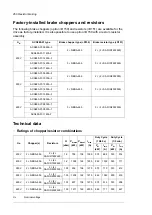


Resistance of specified resistors (per chopper). This is also the minimum allowed resistance for the
resistor assembly.
R
Maximum short-term (1 min every 10 mins) braking power
P
brmax
Maximum continuous power rating
P
brcont
Maximum peak current
I
max
Maximum braking power for the specified duty cycle
P
br
Rms current for the specified duty cycle
I
rms
■
SAFUR resistor data
IPxx
P
Rcont
(kW)
E
R
(kJ)
R
(ohm)
U
N
(V)
Type
IP00
9.0
3600
4.0
500
SAFUR125F500
IP00
10.5
4200
3.4
575
SAFUR210F575
IP00
13.5
5400
2.7
500
SAFUR200F500
IP00
15.0
6000
2.4
460
SAFUR180F460
Nominal voltage
U
N
Resistance
R
Short energy pulse that the resistor assembly will withstand each 400 seconds
E
R
Continuous power (heat) dissipation of the resistor whenplaced correctly. Energy
E
R
dissipates in
400 seconds.
P
Rcont
Degree of protection
IPxx
■
Terminals and cable lead-through data of factory-installed
chopper/resistor cubicles
See the dimension drawings delivered with the unit.
Planning the braking system
■
Verifying the load capacity of the braking equipment
1.
Calculate the maximum power generated by the motor during braking (
P
max
).
2.
Ensure that the maximum power rating of the braking equipment is equal to or greater
than
P
max
.
The
P
brmax
values specified in the ratings table are for the reference braking cycle
(1 minute of braking, 9 minutes of rest). If the actual duty cycle does not correspond to
the reference cycle, either use the power rating given for the other two reference cycles
(
P
br
), or calculate the maximum braking power for a custom braking cycle. See below
for instructions on calculating
P
br
for other braking cycles.
3.
Check the resistor selection. The energy generated by the motor during a 400-second
period must not exceed the heat dissipation capacity of the resistor (
E
R
). If you use
custom resistor(s), see also the separate instructions below.
If the
E
R
value of the resistor is not sufficient, it is possible to use a four-resistor assembly
in which two resistors are connected in parallel, two in series. The
E
R
value of the
four-resistor assembly is four times that of a single resistor.
Resistor braking 267
Summary of Contents for ACS880-07
Page 1: ...ABB industrial drives Hardware manual ACS880 07 drives 560 to 2800 kW ...
Page 2: ......
Page 4: ......
Page 22: ...22 ...
Page 28: ...28 ...
Page 94: ...94 ...
Page 112: ...Electrical installation 109 5 6 4 3 112 Electrical installation ...
Page 113: ...110 Electrical installation 7 8 8 Electrical installation 113 ...
Page 114: ...Electrical installation 111 9 10 114 Electrical installation ...
Page 116: ...Electrical installation 113 4 5 3 6 7 116 Electrical installation ...
Page 118: ...2 11 b PE 10 7 5 6 8 a 360 grounding detail 118 Electrical installation ...
Page 128: ...128 ...
Page 146: ...146 ...
Page 148: ...148 ...
Page 159: ...12 Install and tighten the two M4 12 T20 screws 10 11 12 Maintenance 159 ...
Page 162: ...6 6a 6a 6b 7a 7b 7 8 8a 8b 162 Maintenance ...
Page 166: ...166 Maintenance 6 6 7 8 7 166 Maintenance ...
Page 173: ...6 Reinstall the cover removed earlier and close the cubicle door 4 4 D7T D8T Maintenance 173 ...
Page 213: ... Dimension drawing examples Frame 2 D7T 2 R8i 12 pulse A004 Dimensions 213 ...
Page 214: ...Frame 1 D8T 2 R8i IP22 214 Dimensions ...
Page 215: ...Frame 1 D8T 2 R8i IP54 B055 Dimensions 215 ...
Page 216: ...Frame 1 D8T 2 R8i with common motor terminal cubicle H359 1 2 216 Dimensions ...
Page 217: ...Frame 1 D8T 2 R8i with common motor terminal cubicle H359 2 2 Dimensions 217 ...
Page 218: ...Frame 1 D8T 2 R8i with brake choppers and resistors D150 D151 1 2 218 Dimensions ...
Page 219: ...Frame 1 D8T 2 R8i with brake choppers and resistors D150 D151 2 2 Dimensions 219 ...
Page 220: ...Frame 1 D8T 2 R8i with sine output filter E206 1 2 220 Dimensions ...
Page 221: ...Frame 1 D8T 2 R8i with sine output filter E206 2 2 Dimensions 221 ...
Page 222: ...Frame 2 D8T 2 R8i 12 pulse A004 with grounding switch F259 222 Dimensions ...
Page 223: ...Frame 2 D8T 3 R8i 1 2 Dimensions 223 ...
Page 224: ...Frame 2 D8T 3 R8i 2 2 224 Dimensions ...
Page 225: ...Frame 2 D8T 3 R8i with common motor terminal cubicle H359 1 2 Dimensions 225 ...
Page 226: ...Frame 2 D8T 3 R8i with common motor terminal cubicle H359 2 2 226 Dimensions ...
Page 227: ...Frame 2 D8T 3 R8i with top entry top exit H351 H353 1 2 Dimensions 227 ...
Page 228: ...Frame 2 D8T 3 R8i with top entry top exit 2 2 228 Dimensions ...
Page 229: ...Frame 3 D8T 4 R8i 1 2 Dimensions 229 ...
Page 230: ...Frame 3 D8T 4 R8i 2 2 230 Dimensions ...
Page 231: ...Frame 3 D8T 4 R8i with common motor terminal cubicle H359 1 2 Dimensions 231 ...
Page 232: ...Frame 3 D8T 4 R8i with common motor terminal cubicle H359 2 2 232 Dimensions ...
Page 233: ...Frame 3 D8T 4 R8i with top entry top exit H351 H353 1 2 Dimensions 233 ...
Page 234: ...Frame 3 D8T 4 R8i with top entry top exit H351 H353 2 2 234 Dimensions ...
Page 235: ...Frame 4 D8T 5 R8i 6 pulse with top entry exit UL Listed C129 1 2 Dimensions 235 ...
Page 236: ...Frame 4 D8T 5 R8i 6 pulse with top entry exit UL Listed C129 2 2 236 Dimensions ...
Page 237: ... Dimensions of empty cubicles options C199 C200 C201 IP22 IP42 Dimensions 237 ...
Page 238: ...IP54 238 Dimensions ...
Page 243: ... 1000 mm UL CSA top cable entry Dimensions 243 ...
Page 244: ... 1000 mm UL CSA bottom cable entry 244 Dimensions ...
Page 264: ...264 ...
Page 272: ... 272 ...


