


Technical data
Contents of this chapter
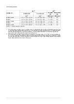
This chapter contains the technical specifications of the drive, for example, the ratings, fuse
data, sizes and technical requirements, provisions for fulfilling the requirements for CE and
other markings.
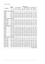
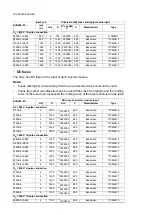
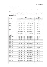
Ratings
The nominal ratings for the drives with 50 Hz and 60 Hz supply are given below. The symbols
are described below the table.
Output ratings
Input
rating
ACS880-07-…
Heavy-duty use
Light-overload use
No-overload use
P
Hd
I
Hd
P
Ld
I
Ld
S
N
P
N
I
max
I
N
I
1
hp
kW
A
hp
kW
A
kVA
hp
kW
A
A
A
U
N
= 400 V, 6-pulse connection
–
400
787
–
560
1072
790
–
630
1482
1140
1047
1140A-3
–
500
935
–
630
1200
866
–
710
1630
1250
1148
1250A-3
–
630
1107
–
800
1421
1025
–
800
1930
1480
1359
1480A-3
–
710
1316
–
900
1690
1219
–
1000
2120
1760
1617
1760A-3
–
900
1653
–
1200
2122
1531
–
1200
2880
2210
2030
2210A-3
–
1000
1952
–
1400
2506
1808
–
1400
3140
2610
2397
2610A-3
U
N
= 400 V, 12-pulse connection
–
400
741
–
500
950
686
–
560
1287
990
909
0990A-3+A004
–
450
853
–
560
1094
790
–
630
1482
1140
1047
1140A-3+A004
–
500
935
–
630
1200
866
–
710
1630
1250
1148
1250A-3+A004
–
630
1107
–
800
1421
1025
–
800
1930
1480
1359
1480A-3+A004
–
710
1316
–
900
1690
1219
–
1000
2120
1760
1617
1760A-3+A004
–
900
1653
–
1200
2122
1531
–
1200
2880
2210
2030
2210A-3+A004
–
1000
1952
–
1400
2506
1808
–
1400
3140
2610
2397
2610A-3+A004
12
Technical data 177
Summary of Contents for ACS880-07
Page 1: ...ABB industrial drives Hardware manual ACS880 07 drives 560 to 2800 kW ...
Page 2: ......
Page 4: ......
Page 22: ...22 ...
Page 28: ...28 ...
Page 94: ...94 ...
Page 112: ...Electrical installation 109 5 6 4 3 112 Electrical installation ...
Page 113: ...110 Electrical installation 7 8 8 Electrical installation 113 ...
Page 114: ...Electrical installation 111 9 10 114 Electrical installation ...
Page 116: ...Electrical installation 113 4 5 3 6 7 116 Electrical installation ...
Page 118: ...2 11 b PE 10 7 5 6 8 a 360 grounding detail 118 Electrical installation ...
Page 128: ...128 ...
Page 146: ...146 ...
Page 148: ...148 ...
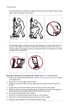
Page 159: ...12 Install and tighten the two M4 12 T20 screws 10 11 12 Maintenance 159 ...
Page 162: ...6 6a 6a 6b 7a 7b 7 8 8a 8b 162 Maintenance ...
Page 166: ...166 Maintenance 6 6 7 8 7 166 Maintenance ...
Page 173: ...6 Reinstall the cover removed earlier and close the cubicle door 4 4 D7T D8T Maintenance 173 ...
Page 213: ... Dimension drawing examples Frame 2 D7T 2 R8i 12 pulse A004 Dimensions 213 ...
Page 214: ...Frame 1 D8T 2 R8i IP22 214 Dimensions ...
Page 215: ...Frame 1 D8T 2 R8i IP54 B055 Dimensions 215 ...
Page 216: ...Frame 1 D8T 2 R8i with common motor terminal cubicle H359 1 2 216 Dimensions ...
Page 217: ...Frame 1 D8T 2 R8i with common motor terminal cubicle H359 2 2 Dimensions 217 ...
Page 218: ...Frame 1 D8T 2 R8i with brake choppers and resistors D150 D151 1 2 218 Dimensions ...
Page 219: ...Frame 1 D8T 2 R8i with brake choppers and resistors D150 D151 2 2 Dimensions 219 ...
Page 220: ...Frame 1 D8T 2 R8i with sine output filter E206 1 2 220 Dimensions ...
Page 221: ...Frame 1 D8T 2 R8i with sine output filter E206 2 2 Dimensions 221 ...
Page 222: ...Frame 2 D8T 2 R8i 12 pulse A004 with grounding switch F259 222 Dimensions ...
Page 223: ...Frame 2 D8T 3 R8i 1 2 Dimensions 223 ...
Page 224: ...Frame 2 D8T 3 R8i 2 2 224 Dimensions ...
Page 225: ...Frame 2 D8T 3 R8i with common motor terminal cubicle H359 1 2 Dimensions 225 ...
Page 226: ...Frame 2 D8T 3 R8i with common motor terminal cubicle H359 2 2 226 Dimensions ...
Page 227: ...Frame 2 D8T 3 R8i with top entry top exit H351 H353 1 2 Dimensions 227 ...
Page 228: ...Frame 2 D8T 3 R8i with top entry top exit 2 2 228 Dimensions ...
Page 229: ...Frame 3 D8T 4 R8i 1 2 Dimensions 229 ...
Page 230: ...Frame 3 D8T 4 R8i 2 2 230 Dimensions ...
Page 231: ...Frame 3 D8T 4 R8i with common motor terminal cubicle H359 1 2 Dimensions 231 ...
Page 232: ...Frame 3 D8T 4 R8i with common motor terminal cubicle H359 2 2 232 Dimensions ...
Page 233: ...Frame 3 D8T 4 R8i with top entry top exit H351 H353 1 2 Dimensions 233 ...
Page 234: ...Frame 3 D8T 4 R8i with top entry top exit H351 H353 2 2 234 Dimensions ...
Page 235: ...Frame 4 D8T 5 R8i 6 pulse with top entry exit UL Listed C129 1 2 Dimensions 235 ...
Page 236: ...Frame 4 D8T 5 R8i 6 pulse with top entry exit UL Listed C129 2 2 236 Dimensions ...
Page 237: ... Dimensions of empty cubicles options C199 C200 C201 IP22 IP42 Dimensions 237 ...
Page 238: ...IP54 238 Dimensions ...
Page 243: ... 1000 mm UL CSA top cable entry Dimensions 243 ...
Page 244: ... 1000 mm UL CSA bottom cable entry 244 Dimensions ...
Page 264: ...264 ...
Page 272: ... 272 ...


