


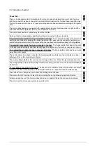


Action
Setting up the inverter unit parameters, and performing the first start
Set up the inverter control program. See the appropriate start-up guide and/or firmware manual. There
is a separate start-up guide only for some control programs.
Check that parameter
95.09 Fuse switch control
is disabled.
Drives with a brake chopper (D150): See chapter
Drives with a sine output filter (E206): Check that bit 1 of parameter
95.15 Special HW settings
is activated.
Drives with an fieldbus adapter module (optional): Set the fieldbus parameters. Activate the appropriate
assistant (if present) in the control program, or see the user’s manual of the fieldbus adapter module,
and the drive firmware manual.
Check that the communication works between the drive and the PLC.
Drives with an encoder interface module (optional): Set the encoder parameters. Activate the appropriate
assistant (if present) in the control program, or see the user’s manual of the encoder interface module,
and the drive firmware manual.
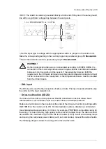
Powering up the main circuit of the drive
Switch the grounding switch (Q9.1) (F259) off.
12-pulse units have two grounding switches, Q9.1 and Q9.2.
Close the main switch-disconnector (Q1.1) or main breaker (Q1).
Note:
Do not use excessive force. The main switch-disconnector (or main breaker) can only be closed when
• the main input terminals (L1, L2, L3) are powered, and
• auxiliary voltage is switched on (Q21), and
• grounding switch is off (Q9.1, Q9.2) (F259).
Turn the operating switch (S21) to the ON (1) position to activate the run enable signal. Depending on
control source settings, this may also close the main contactor (if present). If a main contactor is present
and does not close, refer to the circuit diagrams delivered by the drive as well as the appropriate firmware
manuals.
On-load checks
Start the motor to perform the ID run.
Check that the cooling fans rotate freely in the right direction, and the air flows upwards.
Check that the motor starts. stops and follows the speed reference in the correct direction when controlled
with the control panel.
Check that the motor starts. stops and follows the speed reference in the correct direction when controlled
through the customer-specific I/O or fieldbus.
Drives in which the Safe torque off control circuit is in use: Test and validate the operation of the Safe
torque off function. See section
Start-up including acceptance test (page 258)
Drives with an emergency stop circuit (oQ951, +Q952, +Q963, +Q964, +Q978, +Q979): Test
and validate the operation of the emergency-stop circuit. See the delivery specific circuit diagrams and
wiring, start-up and operating instructions of the option.
Drives with the Prevention of unexpected start-up with safety relay (Q957): Test and validate
the operation of the Prevention of unexpected start-up circuit. See the delivery specific circuit diagrams
and wiring, start-up and operating instructions of the option.
Test and validate the operation of Prevention of unexpected start with FSO-xx (Q950): Test
and validate the operation of the Prevention of unexpected start-up circuit. See the delivery specific
circuit diagrams and wiring, start-up and operating instructions of the option.
Start-up 145
Summary of Contents for ACS880-07
Page 1: ...ABB industrial drives Hardware manual ACS880 07 drives 560 to 2800 kW ...
Page 2: ......
Page 4: ......
Page 22: ...22 ...
Page 28: ...28 ...
Page 94: ...94 ...
Page 112: ...Electrical installation 109 5 6 4 3 112 Electrical installation ...
Page 113: ...110 Electrical installation 7 8 8 Electrical installation 113 ...
Page 114: ...Electrical installation 111 9 10 114 Electrical installation ...
Page 116: ...Electrical installation 113 4 5 3 6 7 116 Electrical installation ...
Page 118: ...2 11 b PE 10 7 5 6 8 a 360 grounding detail 118 Electrical installation ...
Page 128: ...128 ...
Page 146: ...146 ...
Page 148: ...148 ...
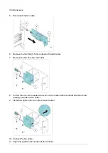
Page 159: ...12 Install and tighten the two M4 12 T20 screws 10 11 12 Maintenance 159 ...
Page 162: ...6 6a 6a 6b 7a 7b 7 8 8a 8b 162 Maintenance ...
Page 166: ...166 Maintenance 6 6 7 8 7 166 Maintenance ...
Page 173: ...6 Reinstall the cover removed earlier and close the cubicle door 4 4 D7T D8T Maintenance 173 ...
Page 213: ... Dimension drawing examples Frame 2 D7T 2 R8i 12 pulse A004 Dimensions 213 ...
Page 214: ...Frame 1 D8T 2 R8i IP22 214 Dimensions ...
Page 215: ...Frame 1 D8T 2 R8i IP54 B055 Dimensions 215 ...
Page 216: ...Frame 1 D8T 2 R8i with common motor terminal cubicle H359 1 2 216 Dimensions ...
Page 217: ...Frame 1 D8T 2 R8i with common motor terminal cubicle H359 2 2 Dimensions 217 ...
Page 218: ...Frame 1 D8T 2 R8i with brake choppers and resistors D150 D151 1 2 218 Dimensions ...
Page 219: ...Frame 1 D8T 2 R8i with brake choppers and resistors D150 D151 2 2 Dimensions 219 ...
Page 220: ...Frame 1 D8T 2 R8i with sine output filter E206 1 2 220 Dimensions ...
Page 221: ...Frame 1 D8T 2 R8i with sine output filter E206 2 2 Dimensions 221 ...
Page 222: ...Frame 2 D8T 2 R8i 12 pulse A004 with grounding switch F259 222 Dimensions ...
Page 223: ...Frame 2 D8T 3 R8i 1 2 Dimensions 223 ...
Page 224: ...Frame 2 D8T 3 R8i 2 2 224 Dimensions ...
Page 225: ...Frame 2 D8T 3 R8i with common motor terminal cubicle H359 1 2 Dimensions 225 ...
Page 226: ...Frame 2 D8T 3 R8i with common motor terminal cubicle H359 2 2 226 Dimensions ...
Page 227: ...Frame 2 D8T 3 R8i with top entry top exit H351 H353 1 2 Dimensions 227 ...
Page 228: ...Frame 2 D8T 3 R8i with top entry top exit 2 2 228 Dimensions ...
Page 229: ...Frame 3 D8T 4 R8i 1 2 Dimensions 229 ...
Page 230: ...Frame 3 D8T 4 R8i 2 2 230 Dimensions ...
Page 231: ...Frame 3 D8T 4 R8i with common motor terminal cubicle H359 1 2 Dimensions 231 ...
Page 232: ...Frame 3 D8T 4 R8i with common motor terminal cubicle H359 2 2 232 Dimensions ...
Page 233: ...Frame 3 D8T 4 R8i with top entry top exit H351 H353 1 2 Dimensions 233 ...
Page 234: ...Frame 3 D8T 4 R8i with top entry top exit H351 H353 2 2 234 Dimensions ...
Page 235: ...Frame 4 D8T 5 R8i 6 pulse with top entry exit UL Listed C129 1 2 Dimensions 235 ...
Page 236: ...Frame 4 D8T 5 R8i 6 pulse with top entry exit UL Listed C129 2 2 236 Dimensions ...
Page 237: ... Dimensions of empty cubicles options C199 C200 C201 IP22 IP42 Dimensions 237 ...
Page 238: ...IP54 238 Dimensions ...
Page 243: ... 1000 mm UL CSA top cable entry Dimensions 243 ...
Page 244: ... 1000 mm UL CSA bottom cable entry 244 Dimensions ...
Page 264: ...264 ...
Page 272: ... 272 ...


