


•
If you are not a qualified electrician, do not do electrical installation or maintenance
work.
•
Do not install the drive if the electrical power network, motor/generator, or environmental
conditions do not agree with the drive data.
•
Do not install a drive with EMC filter (E200 or +E202) on an ungrounded power
system or a high resistance-grounded (over 30 ohms) power system.
•
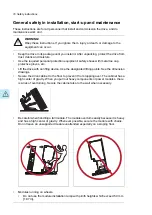
We do not recommend that you secure the cabinet by arc welding. If you have to, obey
the separate welding instructions in the drive manuals.
•
Do not do insulation or voltage withstand tests on the drive.
Note:
•
The motor cable terminals of the drive are at a dangerous voltage when the input power
is on, regardless of whether the motor is running or not.
•
When the input power is on, the drive DC bus is at a dangerous voltage. If brake chopper
and resistor are in use, they are also at a dangerous voltage. (D150)
•
External wiring can supply dangerous voltages to the relay outputs of the control units
of the drive.
•
The Safe torque off function does not remove the voltage from the main and auxiliary
circuits. The function is not effective against deliberate sabotage or misuse.
WARNING!
Obey these instructions. If you ignore them, damage to the equipment can occur.
•
Handle fiber optic cables with care:
•
When you unplug the cables, always hold the connector, not the cable itself.
•
Do not touch the ends of the fibers with bare hands as the ends are extremely
sensitive to dirt.
•
Do not bend the fiber optic cables too tightly. The minimum allowed bend radius is
35 mm (1.4”).
WARNING!
Use a grounding wrist band when you handle printed circuit boards. Do not touch
the boards unnecessarily. The boards contain components sensitive to electrostatic
discharge.
■
Grounding
These instructions are for all personnel who are responsible for the grounding of the drive.
WARNING!
Obey these instructions. If you ignore them, injury or death, or equipment
malfunction can occur, and electromagnetic interference can increase.
•
If you are not a qualified electrician, do not do grounding work.
•
Always ground the drive, the motor and adjoining equipment. This is necessary for the
personnel safety. Proper grounding also reduces electromagnetic emission and
interference.
•
Make sure that the conductivity of the grounding conductors is sufficient. See electrical
planning instructions. Obey the local regulations.
20 Safety instructions
Summary of Contents for ACS880-07
Page 1: ...ABB industrial drives Hardware manual ACS880 07 drives 560 to 2800 kW ...
Page 2: ......
Page 4: ......
Page 22: ...22 ...
Page 28: ...28 ...
Page 94: ...94 ...
Page 112: ...Electrical installation 109 5 6 4 3 112 Electrical installation ...
Page 113: ...110 Electrical installation 7 8 8 Electrical installation 113 ...
Page 114: ...Electrical installation 111 9 10 114 Electrical installation ...
Page 116: ...Electrical installation 113 4 5 3 6 7 116 Electrical installation ...
Page 118: ...2 11 b PE 10 7 5 6 8 a 360 grounding detail 118 Electrical installation ...
Page 128: ...128 ...
Page 146: ...146 ...
Page 148: ...148 ...
Page 159: ...12 Install and tighten the two M4 12 T20 screws 10 11 12 Maintenance 159 ...
Page 162: ...6 6a 6a 6b 7a 7b 7 8 8a 8b 162 Maintenance ...
Page 166: ...166 Maintenance 6 6 7 8 7 166 Maintenance ...
Page 173: ...6 Reinstall the cover removed earlier and close the cubicle door 4 4 D7T D8T Maintenance 173 ...
Page 213: ... Dimension drawing examples Frame 2 D7T 2 R8i 12 pulse A004 Dimensions 213 ...
Page 214: ...Frame 1 D8T 2 R8i IP22 214 Dimensions ...
Page 215: ...Frame 1 D8T 2 R8i IP54 B055 Dimensions 215 ...
Page 216: ...Frame 1 D8T 2 R8i with common motor terminal cubicle H359 1 2 216 Dimensions ...
Page 217: ...Frame 1 D8T 2 R8i with common motor terminal cubicle H359 2 2 Dimensions 217 ...
Page 218: ...Frame 1 D8T 2 R8i with brake choppers and resistors D150 D151 1 2 218 Dimensions ...
Page 219: ...Frame 1 D8T 2 R8i with brake choppers and resistors D150 D151 2 2 Dimensions 219 ...
Page 220: ...Frame 1 D8T 2 R8i with sine output filter E206 1 2 220 Dimensions ...
Page 221: ...Frame 1 D8T 2 R8i with sine output filter E206 2 2 Dimensions 221 ...
Page 222: ...Frame 2 D8T 2 R8i 12 pulse A004 with grounding switch F259 222 Dimensions ...
Page 223: ...Frame 2 D8T 3 R8i 1 2 Dimensions 223 ...
Page 224: ...Frame 2 D8T 3 R8i 2 2 224 Dimensions ...
Page 225: ...Frame 2 D8T 3 R8i with common motor terminal cubicle H359 1 2 Dimensions 225 ...
Page 226: ...Frame 2 D8T 3 R8i with common motor terminal cubicle H359 2 2 226 Dimensions ...
Page 227: ...Frame 2 D8T 3 R8i with top entry top exit H351 H353 1 2 Dimensions 227 ...
Page 228: ...Frame 2 D8T 3 R8i with top entry top exit 2 2 228 Dimensions ...
Page 229: ...Frame 3 D8T 4 R8i 1 2 Dimensions 229 ...
Page 230: ...Frame 3 D8T 4 R8i 2 2 230 Dimensions ...
Page 231: ...Frame 3 D8T 4 R8i with common motor terminal cubicle H359 1 2 Dimensions 231 ...
Page 232: ...Frame 3 D8T 4 R8i with common motor terminal cubicle H359 2 2 232 Dimensions ...
Page 233: ...Frame 3 D8T 4 R8i with top entry top exit H351 H353 1 2 Dimensions 233 ...
Page 234: ...Frame 3 D8T 4 R8i with top entry top exit H351 H353 2 2 234 Dimensions ...
Page 235: ...Frame 4 D8T 5 R8i 6 pulse with top entry exit UL Listed C129 1 2 Dimensions 235 ...
Page 236: ...Frame 4 D8T 5 R8i 6 pulse with top entry exit UL Listed C129 2 2 236 Dimensions ...
Page 237: ... Dimensions of empty cubicles options C199 C200 C201 IP22 IP42 Dimensions 237 ...
Page 238: ...IP54 238 Dimensions ...
Page 243: ... 1000 mm UL CSA top cable entry Dimensions 243 ...
Page 244: ... 1000 mm UL CSA bottom cable entry 244 Dimensions ...
Page 264: ...264 ...
Page 272: ... 272 ...


