


Name
Standard
Functional safety of electrical/electronic/programmable electronic safety-
related systems – Part 1: General requirements
IEC 61508-1:2010
Functional safety of electrical/electronic/programmable electronic safety-
related systems – Part 2: Requirements for electrical/electronic/program-
mable electronic safety-related systems
IEC 61508-2:2010
Functional safety – Safety instrumented systems for the process industry
sector
IEC 61511-1:2016
Adjustable speed electrical power drive systems – Part 5-2: Safety require-
ments – Functional
IEC 61800-5-2:2016
EN 61800-5-2:2007
Safety of machinery – Functional safety of safety-related electrical, elec-
tronic and programmable electronic control systems
IEC 62061:2015
EN 62061:2005
+AC:2010+A1:2013+A2:2015
Safety of machinery – Safety-related parts of control systems – Part 1:
General principles for design
EN ISO 13849-1:2015
Safety of machinery – Safety-related parts of control systems – Part 2:
Validation
EN ISO 13849-2:2012
The function also corresponds to Prevention of unexpected start-up as specified by
EN 1037:1995 + A1:2008 and Uncontrolled stop (stop category 0) as specified in
EN/IEC 60204-1.
■
Compliance with the European Machinery Directive
Compliance with the European Machinery Directive (page 197)
Wiring
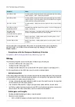
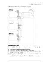
The following diagrams present examples of Safe torque off wiring for
•
a frame n×R8i inverter unit (page
•
multiple inverter units (page
•
multiple inverter units when an external 24 V DC power supply is used (page
For the specification of the STO input, see the control unit description.
■
Activation switch
In the wiring diagrams below, the activation switch has the designation [K]. This represents
a component such as a manually operated switch, an emergency stop push button switch,
or the contacts of a safety relay or safety PLC.
•
In case a manually operated activation switch is used, the switch must be of a type that
can be locked out to the open position.
•
The contacts of the switch or relay must open/close within 200 ms of each other.
•
An FSO-xx safety functions module or and FPTC-0x thermistor protection module can
also be used. For more information, see the module documentation.
■
Cable types and lengths
•
Double-shielded twisted-pair cable is recommended.
•
Maximum cable lengths:
•
300 m (1000 ft) between activation switch [K] and inverter control unit
254 The Safe torque off function
Summary of Contents for ACS880-07
Page 1: ...ABB industrial drives Hardware manual ACS880 07 drives 560 to 2800 kW ...
Page 2: ......
Page 4: ......
Page 22: ...22 ...
Page 28: ...28 ...
Page 94: ...94 ...
Page 112: ...Electrical installation 109 5 6 4 3 112 Electrical installation ...
Page 113: ...110 Electrical installation 7 8 8 Electrical installation 113 ...
Page 114: ...Electrical installation 111 9 10 114 Electrical installation ...
Page 116: ...Electrical installation 113 4 5 3 6 7 116 Electrical installation ...
Page 118: ...2 11 b PE 10 7 5 6 8 a 360 grounding detail 118 Electrical installation ...
Page 128: ...128 ...
Page 146: ...146 ...
Page 148: ...148 ...
Page 159: ...12 Install and tighten the two M4 12 T20 screws 10 11 12 Maintenance 159 ...
Page 162: ...6 6a 6a 6b 7a 7b 7 8 8a 8b 162 Maintenance ...
Page 166: ...166 Maintenance 6 6 7 8 7 166 Maintenance ...
Page 173: ...6 Reinstall the cover removed earlier and close the cubicle door 4 4 D7T D8T Maintenance 173 ...
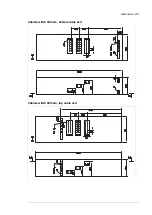
Page 213: ... Dimension drawing examples Frame 2 D7T 2 R8i 12 pulse A004 Dimensions 213 ...
Page 214: ...Frame 1 D8T 2 R8i IP22 214 Dimensions ...
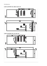
Page 215: ...Frame 1 D8T 2 R8i IP54 B055 Dimensions 215 ...
Page 216: ...Frame 1 D8T 2 R8i with common motor terminal cubicle H359 1 2 216 Dimensions ...
Page 217: ...Frame 1 D8T 2 R8i with common motor terminal cubicle H359 2 2 Dimensions 217 ...
Page 218: ...Frame 1 D8T 2 R8i with brake choppers and resistors D150 D151 1 2 218 Dimensions ...
Page 219: ...Frame 1 D8T 2 R8i with brake choppers and resistors D150 D151 2 2 Dimensions 219 ...
Page 220: ...Frame 1 D8T 2 R8i with sine output filter E206 1 2 220 Dimensions ...
Page 221: ...Frame 1 D8T 2 R8i with sine output filter E206 2 2 Dimensions 221 ...
Page 222: ...Frame 2 D8T 2 R8i 12 pulse A004 with grounding switch F259 222 Dimensions ...
Page 223: ...Frame 2 D8T 3 R8i 1 2 Dimensions 223 ...
Page 224: ...Frame 2 D8T 3 R8i 2 2 224 Dimensions ...
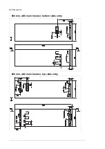
Page 225: ...Frame 2 D8T 3 R8i with common motor terminal cubicle H359 1 2 Dimensions 225 ...
Page 226: ...Frame 2 D8T 3 R8i with common motor terminal cubicle H359 2 2 226 Dimensions ...
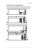
Page 227: ...Frame 2 D8T 3 R8i with top entry top exit H351 H353 1 2 Dimensions 227 ...
Page 228: ...Frame 2 D8T 3 R8i with top entry top exit 2 2 228 Dimensions ...
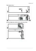
Page 229: ...Frame 3 D8T 4 R8i 1 2 Dimensions 229 ...
Page 230: ...Frame 3 D8T 4 R8i 2 2 230 Dimensions ...
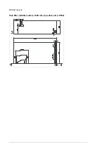
Page 231: ...Frame 3 D8T 4 R8i with common motor terminal cubicle H359 1 2 Dimensions 231 ...
Page 232: ...Frame 3 D8T 4 R8i with common motor terminal cubicle H359 2 2 232 Dimensions ...
Page 233: ...Frame 3 D8T 4 R8i with top entry top exit H351 H353 1 2 Dimensions 233 ...
Page 234: ...Frame 3 D8T 4 R8i with top entry top exit H351 H353 2 2 234 Dimensions ...
Page 235: ...Frame 4 D8T 5 R8i 6 pulse with top entry exit UL Listed C129 1 2 Dimensions 235 ...
Page 236: ...Frame 4 D8T 5 R8i 6 pulse with top entry exit UL Listed C129 2 2 236 Dimensions ...
Page 237: ... Dimensions of empty cubicles options C199 C200 C201 IP22 IP42 Dimensions 237 ...
Page 238: ...IP54 238 Dimensions ...
Page 243: ... 1000 mm UL CSA top cable entry Dimensions 243 ...
Page 244: ... 1000 mm UL CSA bottom cable entry 244 Dimensions ...
Page 264: ...264 ...
Page 272: ... 272 ...


