


■
Selecting and routing the cables of a custom resistor
Use the same cable type for the resistor cabling as for the drive input cabling to ensure that
the input fuses also protect the resistor cable. Alternatively, a two conductor shielded cable
with the same cross-sectional area can be used.
Minimizing electromagnetic interference
Follow these rules in order to minimize electromagnetic interference caused by the rapid
current changes in the resistor cables:
•
Shield the braking power line completely, either by using shielded cable or a metallic
enclosure. Unshielded single-core cable can only be used if it is routed inside a cabinet
that efficiently suppresses the radiated emissions.
•
Install the cables away from other cable routes.
•
Avoid long parallel runs with other cables. The minimum parallel cabling separation
distance should be 0.3 meters (1 ft).
•
Cross any other cables at right angles.
•
Keep the cable as short as possible in order to minimize the radiated emissions and
stress on chopper IGBTs. The longer the cable the higher the radiated emissions,
inductive load and voltage peaks over the IGBT semiconductors of the brake chopper.
Note:
ABB has not verified that the EMC requirements are fulfilled with custom brake resistors
and cabling. The customer must consider the EMC compliance of the complete installation.
Maximum cable length
The maximum length of the resistor cable(s) is 50 m (164 ft).
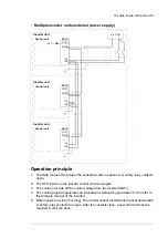
■
Placing custom brake resistors
Install the resistors outside the drive in a place where they are able to cool effectively.
Arrange the cooling of the resistor in a way that
•
no danger of overheating is caused to the resistor or nearby materials, and
•
the temperature of the room the resistor is located in does not exceed the allowed
maximum.
Supply the resistor with cooling air/water according to the resistor manufacturer’s instructions.
WARNING!
The materials near the brake resistor must be non-flammable. The surface
temperature of the resistor is high. The temperature of the air flowing from the
resistor is hundreds of degrees Celsius. If the exhaust vents are connected to a
ventilation system, ensure that the materials withstand high temperatures. Protect
the resistor against contact.
■
Protecting the brake system against thermal overload
The brake chopper protects itself and the resistor cables against thermal overload when
the cables are dimensioned according to the nominal current of the drive. By default, a brake
chopper fault is wired to stop the supply unit of the drive.
Resistor braking 269
Summary of Contents for ACS880-07
Page 1: ...ABB industrial drives Hardware manual ACS880 07 drives 560 to 2800 kW ...
Page 2: ......
Page 4: ......
Page 22: ...22 ...
Page 28: ...28 ...
Page 94: ...94 ...
Page 112: ...Electrical installation 109 5 6 4 3 112 Electrical installation ...
Page 113: ...110 Electrical installation 7 8 8 Electrical installation 113 ...
Page 114: ...Electrical installation 111 9 10 114 Electrical installation ...
Page 116: ...Electrical installation 113 4 5 3 6 7 116 Electrical installation ...
Page 118: ...2 11 b PE 10 7 5 6 8 a 360 grounding detail 118 Electrical installation ...
Page 128: ...128 ...
Page 146: ...146 ...
Page 148: ...148 ...
Page 159: ...12 Install and tighten the two M4 12 T20 screws 10 11 12 Maintenance 159 ...
Page 162: ...6 6a 6a 6b 7a 7b 7 8 8a 8b 162 Maintenance ...
Page 166: ...166 Maintenance 6 6 7 8 7 166 Maintenance ...
Page 173: ...6 Reinstall the cover removed earlier and close the cubicle door 4 4 D7T D8T Maintenance 173 ...
Page 213: ... Dimension drawing examples Frame 2 D7T 2 R8i 12 pulse A004 Dimensions 213 ...
Page 214: ...Frame 1 D8T 2 R8i IP22 214 Dimensions ...
Page 215: ...Frame 1 D8T 2 R8i IP54 B055 Dimensions 215 ...
Page 216: ...Frame 1 D8T 2 R8i with common motor terminal cubicle H359 1 2 216 Dimensions ...
Page 217: ...Frame 1 D8T 2 R8i with common motor terminal cubicle H359 2 2 Dimensions 217 ...
Page 218: ...Frame 1 D8T 2 R8i with brake choppers and resistors D150 D151 1 2 218 Dimensions ...
Page 219: ...Frame 1 D8T 2 R8i with brake choppers and resistors D150 D151 2 2 Dimensions 219 ...
Page 220: ...Frame 1 D8T 2 R8i with sine output filter E206 1 2 220 Dimensions ...
Page 221: ...Frame 1 D8T 2 R8i with sine output filter E206 2 2 Dimensions 221 ...
Page 222: ...Frame 2 D8T 2 R8i 12 pulse A004 with grounding switch F259 222 Dimensions ...
Page 223: ...Frame 2 D8T 3 R8i 1 2 Dimensions 223 ...
Page 224: ...Frame 2 D8T 3 R8i 2 2 224 Dimensions ...
Page 225: ...Frame 2 D8T 3 R8i with common motor terminal cubicle H359 1 2 Dimensions 225 ...
Page 226: ...Frame 2 D8T 3 R8i with common motor terminal cubicle H359 2 2 226 Dimensions ...
Page 227: ...Frame 2 D8T 3 R8i with top entry top exit H351 H353 1 2 Dimensions 227 ...
Page 228: ...Frame 2 D8T 3 R8i with top entry top exit 2 2 228 Dimensions ...
Page 229: ...Frame 3 D8T 4 R8i 1 2 Dimensions 229 ...
Page 230: ...Frame 3 D8T 4 R8i 2 2 230 Dimensions ...
Page 231: ...Frame 3 D8T 4 R8i with common motor terminal cubicle H359 1 2 Dimensions 231 ...
Page 232: ...Frame 3 D8T 4 R8i with common motor terminal cubicle H359 2 2 232 Dimensions ...
Page 233: ...Frame 3 D8T 4 R8i with top entry top exit H351 H353 1 2 Dimensions 233 ...
Page 234: ...Frame 3 D8T 4 R8i with top entry top exit H351 H353 2 2 234 Dimensions ...
Page 235: ...Frame 4 D8T 5 R8i 6 pulse with top entry exit UL Listed C129 1 2 Dimensions 235 ...
Page 236: ...Frame 4 D8T 5 R8i 6 pulse with top entry exit UL Listed C129 2 2 236 Dimensions ...
Page 237: ... Dimensions of empty cubicles options C199 C200 C201 IP22 IP42 Dimensions 237 ...
Page 238: ...IP54 238 Dimensions ...
Page 243: ... 1000 mm UL CSA top cable entry Dimensions 243 ...
Page 244: ... 1000 mm UL CSA bottom cable entry 244 Dimensions ...
Page 264: ...264 ...
Page 272: ... 272 ...


