


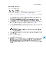


Removing and reinstalling the fan carriage of an inverter module
Refer to the drawings below.
WARNING!
Obey the instructions in chapter
. If you ignore
them, injury or death, or damage to the equipment can occur.
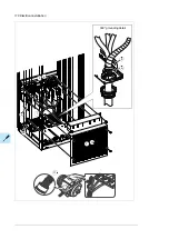
1.
Do the steps in section
Electrical safety precautions (page 19)
before you start the work.
2.
Open the inverter module cubicle door.
3.
Remove the screws holding the front cover plate. Lift the cover plate somewhat to
release it.
4.
Disconnect the wiring at the top of the fan carriage.
5.
Remove the two screws at the bottom of the fan carriage.
WARNING!
Before you proceed, make sure the two screws holding the top of the inverter
module are in place.
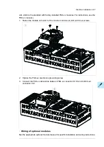
6.
Remove the two screws at the top of the fan carriage.
7.
Pull the fan carriage out.
8.
Repeat the procedure for other fan carriages in the same cubicle.
Proceed to
Connecting the motor cables (page 117)
.
Electrical installation 115
Summary of Contents for ACS880-07
Page 1: ...ABB industrial drives Hardware manual ACS880 07 drives 560 to 2800 kW ...
Page 2: ......
Page 4: ......
Page 22: ...22 ...
Page 28: ...28 ...
Page 94: ...94 ...
Page 112: ...Electrical installation 109 5 6 4 3 112 Electrical installation ...
Page 113: ...110 Electrical installation 7 8 8 Electrical installation 113 ...
Page 114: ...Electrical installation 111 9 10 114 Electrical installation ...
Page 116: ...Electrical installation 113 4 5 3 6 7 116 Electrical installation ...
Page 118: ...2 11 b PE 10 7 5 6 8 a 360 grounding detail 118 Electrical installation ...
Page 128: ...128 ...
Page 146: ...146 ...
Page 148: ...148 ...
Page 159: ...12 Install and tighten the two M4 12 T20 screws 10 11 12 Maintenance 159 ...
Page 162: ...6 6a 6a 6b 7a 7b 7 8 8a 8b 162 Maintenance ...
Page 166: ...166 Maintenance 6 6 7 8 7 166 Maintenance ...
Page 173: ...6 Reinstall the cover removed earlier and close the cubicle door 4 4 D7T D8T Maintenance 173 ...
Page 213: ... Dimension drawing examples Frame 2 D7T 2 R8i 12 pulse A004 Dimensions 213 ...
Page 214: ...Frame 1 D8T 2 R8i IP22 214 Dimensions ...
Page 215: ...Frame 1 D8T 2 R8i IP54 B055 Dimensions 215 ...
Page 216: ...Frame 1 D8T 2 R8i with common motor terminal cubicle H359 1 2 216 Dimensions ...
Page 217: ...Frame 1 D8T 2 R8i with common motor terminal cubicle H359 2 2 Dimensions 217 ...
Page 218: ...Frame 1 D8T 2 R8i with brake choppers and resistors D150 D151 1 2 218 Dimensions ...
Page 219: ...Frame 1 D8T 2 R8i with brake choppers and resistors D150 D151 2 2 Dimensions 219 ...
Page 220: ...Frame 1 D8T 2 R8i with sine output filter E206 1 2 220 Dimensions ...
Page 221: ...Frame 1 D8T 2 R8i with sine output filter E206 2 2 Dimensions 221 ...
Page 222: ...Frame 2 D8T 2 R8i 12 pulse A004 with grounding switch F259 222 Dimensions ...
Page 223: ...Frame 2 D8T 3 R8i 1 2 Dimensions 223 ...
Page 224: ...Frame 2 D8T 3 R8i 2 2 224 Dimensions ...
Page 225: ...Frame 2 D8T 3 R8i with common motor terminal cubicle H359 1 2 Dimensions 225 ...
Page 226: ...Frame 2 D8T 3 R8i with common motor terminal cubicle H359 2 2 226 Dimensions ...
Page 227: ...Frame 2 D8T 3 R8i with top entry top exit H351 H353 1 2 Dimensions 227 ...
Page 228: ...Frame 2 D8T 3 R8i with top entry top exit 2 2 228 Dimensions ...
Page 229: ...Frame 3 D8T 4 R8i 1 2 Dimensions 229 ...
Page 230: ...Frame 3 D8T 4 R8i 2 2 230 Dimensions ...
Page 231: ...Frame 3 D8T 4 R8i with common motor terminal cubicle H359 1 2 Dimensions 231 ...
Page 232: ...Frame 3 D8T 4 R8i with common motor terminal cubicle H359 2 2 232 Dimensions ...
Page 233: ...Frame 3 D8T 4 R8i with top entry top exit H351 H353 1 2 Dimensions 233 ...
Page 234: ...Frame 3 D8T 4 R8i with top entry top exit H351 H353 2 2 234 Dimensions ...
Page 235: ...Frame 4 D8T 5 R8i 6 pulse with top entry exit UL Listed C129 1 2 Dimensions 235 ...
Page 236: ...Frame 4 D8T 5 R8i 6 pulse with top entry exit UL Listed C129 2 2 236 Dimensions ...
Page 237: ... Dimensions of empty cubicles options C199 C200 C201 IP22 IP42 Dimensions 237 ...
Page 238: ...IP54 238 Dimensions ...
Page 243: ... 1000 mm UL CSA top cable entry Dimensions 243 ...
Page 244: ... 1000 mm UL CSA bottom cable entry 244 Dimensions ...
Page 264: ...264 ...
Page 272: ... 272 ...


