


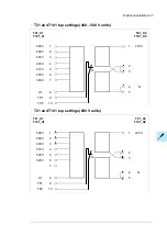


The settings of the FSO-xx are at default when delivered from the factory. The wiring of the
external safety circuit and configuration of the FSO-xx module are the responsibility of the
machine builder.
The FSO-xx reserves the standard Safe torque off (STO) connection of the inverter control
unit. STO can still be utilized by other safety circuits through the FSO-xx.
For wiring instructions, safety data and more information on the functions provided by the
FSO-xx, refer to its manual. See
FSO-12 safety functions module user’s manual
(3AXD50000015612 [English]).
Implementing the Power-loss ride-through
Implement the power-loss ride-through function as follows:
•
Check that the power-loss ride-through function of the inverter unit is enabled with
parameter
30.31 Undervoltage control
in the ACS880 primary control program.
•
Make sure that the control of the main contactor/breaker either keeps the contactor
closed over the short power break, or closes it after the break automatically.
WARNING!
Make sure that the automatic re-connection of the input power does not cause
any danger. If you are in doubt, do not implement the Power-loss ride-through
function.
WARNING!
Make sure that the flying restart of the motor will not cause any danger. If you are
in doubt, do not implement the Power-loss ride-through function.
■
Units with main contactor (F250)
The main contactor of the drive opens in a power-loss situation. When the power returns,
the contactor closes. However, if the power-loss situation lasts so long that the drive trips
on undervoltage, it must be reset and started again to continue operation. If the power-loss
situation lasts so long that the auxiliary power buffer module runs out, the main contactor
remains open and the drive operates only after reset and a new start.
With external uninterruptible control voltage (G307), the main contactor remains
closed in power-loss situations. If the power-loss situation lasts so long that the drive trips
on undervoltage, it must be reset and started again to continue operation.
Implementing a bypass connection
If bypassing is required, employ mechanically or electrically interlocked contactors between
the motor and the drive and between the motor and the power line. Make sure with
interlocking that the contactors cannot be closed simultaneously. The installation must be
clearly marked as defined in IEC/EN 61800-5-1, subclause 6.5.3, for example, “THIS
MACHINE STARTS AUTOMATICALLY”.
Bypass connection is available as a factory-installed option for certain cabinet-built drive
types. Consult ABB for more information.
90 Guidelines for planning the electrical installation
Summary of Contents for ACS880-07
Page 1: ...ABB industrial drives Hardware manual ACS880 07 drives 560 to 2800 kW ...
Page 2: ......
Page 4: ......
Page 22: ...22 ...
Page 28: ...28 ...
Page 94: ...94 ...
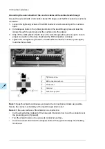
Page 112: ...Electrical installation 109 5 6 4 3 112 Electrical installation ...
Page 113: ...110 Electrical installation 7 8 8 Electrical installation 113 ...
Page 114: ...Electrical installation 111 9 10 114 Electrical installation ...
Page 116: ...Electrical installation 113 4 5 3 6 7 116 Electrical installation ...
Page 118: ...2 11 b PE 10 7 5 6 8 a 360 grounding detail 118 Electrical installation ...
Page 128: ...128 ...
Page 146: ...146 ...
Page 148: ...148 ...
Page 159: ...12 Install and tighten the two M4 12 T20 screws 10 11 12 Maintenance 159 ...
Page 162: ...6 6a 6a 6b 7a 7b 7 8 8a 8b 162 Maintenance ...
Page 166: ...166 Maintenance 6 6 7 8 7 166 Maintenance ...
Page 173: ...6 Reinstall the cover removed earlier and close the cubicle door 4 4 D7T D8T Maintenance 173 ...
Page 213: ... Dimension drawing examples Frame 2 D7T 2 R8i 12 pulse A004 Dimensions 213 ...
Page 214: ...Frame 1 D8T 2 R8i IP22 214 Dimensions ...
Page 215: ...Frame 1 D8T 2 R8i IP54 B055 Dimensions 215 ...
Page 216: ...Frame 1 D8T 2 R8i with common motor terminal cubicle H359 1 2 216 Dimensions ...
Page 217: ...Frame 1 D8T 2 R8i with common motor terminal cubicle H359 2 2 Dimensions 217 ...
Page 218: ...Frame 1 D8T 2 R8i with brake choppers and resistors D150 D151 1 2 218 Dimensions ...
Page 219: ...Frame 1 D8T 2 R8i with brake choppers and resistors D150 D151 2 2 Dimensions 219 ...
Page 220: ...Frame 1 D8T 2 R8i with sine output filter E206 1 2 220 Dimensions ...
Page 221: ...Frame 1 D8T 2 R8i with sine output filter E206 2 2 Dimensions 221 ...
Page 222: ...Frame 2 D8T 2 R8i 12 pulse A004 with grounding switch F259 222 Dimensions ...
Page 223: ...Frame 2 D8T 3 R8i 1 2 Dimensions 223 ...
Page 224: ...Frame 2 D8T 3 R8i 2 2 224 Dimensions ...
Page 225: ...Frame 2 D8T 3 R8i with common motor terminal cubicle H359 1 2 Dimensions 225 ...
Page 226: ...Frame 2 D8T 3 R8i with common motor terminal cubicle H359 2 2 226 Dimensions ...
Page 227: ...Frame 2 D8T 3 R8i with top entry top exit H351 H353 1 2 Dimensions 227 ...
Page 228: ...Frame 2 D8T 3 R8i with top entry top exit 2 2 228 Dimensions ...
Page 229: ...Frame 3 D8T 4 R8i 1 2 Dimensions 229 ...
Page 230: ...Frame 3 D8T 4 R8i 2 2 230 Dimensions ...
Page 231: ...Frame 3 D8T 4 R8i with common motor terminal cubicle H359 1 2 Dimensions 231 ...
Page 232: ...Frame 3 D8T 4 R8i with common motor terminal cubicle H359 2 2 232 Dimensions ...
Page 233: ...Frame 3 D8T 4 R8i with top entry top exit H351 H353 1 2 Dimensions 233 ...
Page 234: ...Frame 3 D8T 4 R8i with top entry top exit H351 H353 2 2 234 Dimensions ...
Page 235: ...Frame 4 D8T 5 R8i 6 pulse with top entry exit UL Listed C129 1 2 Dimensions 235 ...
Page 236: ...Frame 4 D8T 5 R8i 6 pulse with top entry exit UL Listed C129 2 2 236 Dimensions ...
Page 237: ... Dimensions of empty cubicles options C199 C200 C201 IP22 IP42 Dimensions 237 ...
Page 238: ...IP54 238 Dimensions ...
Page 243: ... 1000 mm UL CSA top cable entry Dimensions 243 ...
Page 244: ... 1000 mm UL CSA bottom cable entry 244 Dimensions ...
Page 264: ...264 ...
Page 272: ... 272 ...


