


1
2
3
4
B
A
BGND
SH
IE
L
D
XD
2
D
1
2
3
4
B
A
BGND
SH
IE
L
D
XD
2
D
1
2
3
4
B
A
BGND
SH
IE
L
D
XD
2
D
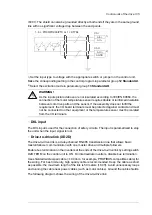
Termination ON
Termination ON
Termination OFF
■
Safe torque off (XSTO, XSTO OUT)
On the inverter control unit (A41), the XSTO input can be used to implement a safe torque
off (STO) function. For the drive to start, both connections (OUT1 to IN1 and IN2) must be
closed. By default, the terminal block has jumpers to close the circuit. Remove the jumpers
before connecting an external Safe torque off circuit to the drive. For information on the
implementation of a Safe torque off function, see chapter
Note:
The XSTO input only acts as a true Safe torque off input on the inverter control unit [A41].
De-energizing the IN1 and/or IN2 terminals on the supply control unit [A51] will stop the
supply unit but not constitute a true safety function.
The XSTO OUT connector is wired to the STO IN connector of one inverter module. In case
the inverter unit consists of multiple modules, the STO OUT connector of one module is
wired to the STO IN connector of the next module etc. so that all modules are part of the
chain.
■
FSO-xx safety functions module connection (X12)
See the user manual of the FSO-xx module.
■
SDHC memory card slot
The BCU-x2 has an on-board data logger that collects real-time data from the power modules
to help fault tracing and analysis. The data is stored onto the SDHC memory card inserted
into the SD CARD slot and can be analyzed by ABB service personnel.
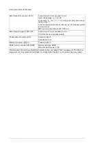
Connector data
Connector pitch 5 mm, wire size 2.5 mm
2
Power supply (XPOW)
24 V (±10%) DC, 2 A
External power input. Two supplies can be connected for redundancy.
Connector pitch 5 mm, wire size 2.5 mm
2
Relay outputs RO1…RO3
(XRO1…XRO3)
250 V AC / 30 V DC, 2 A
Protected by varistors
Connector pitch 5 mm, wire size 2.5 mm
2
+24 V output (XD24:2 and XD24:4)
Total load capacity of these outputs is 4.8 W (200 mA / 24 V) minus
the power taken by DIO1 and DIO2.
136 Control units of the drive
Summary of Contents for ACS880-07
Page 1: ...ABB industrial drives Hardware manual ACS880 07 drives 560 to 2800 kW ...
Page 2: ......
Page 4: ......
Page 22: ...22 ...
Page 28: ...28 ...
Page 94: ...94 ...
Page 112: ...Electrical installation 109 5 6 4 3 112 Electrical installation ...
Page 113: ...110 Electrical installation 7 8 8 Electrical installation 113 ...
Page 114: ...Electrical installation 111 9 10 114 Electrical installation ...
Page 116: ...Electrical installation 113 4 5 3 6 7 116 Electrical installation ...
Page 118: ...2 11 b PE 10 7 5 6 8 a 360 grounding detail 118 Electrical installation ...
Page 128: ...128 ...
Page 146: ...146 ...
Page 148: ...148 ...
Page 159: ...12 Install and tighten the two M4 12 T20 screws 10 11 12 Maintenance 159 ...
Page 162: ...6 6a 6a 6b 7a 7b 7 8 8a 8b 162 Maintenance ...
Page 166: ...166 Maintenance 6 6 7 8 7 166 Maintenance ...
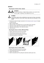
Page 173: ...6 Reinstall the cover removed earlier and close the cubicle door 4 4 D7T D8T Maintenance 173 ...
Page 213: ... Dimension drawing examples Frame 2 D7T 2 R8i 12 pulse A004 Dimensions 213 ...
Page 214: ...Frame 1 D8T 2 R8i IP22 214 Dimensions ...
Page 215: ...Frame 1 D8T 2 R8i IP54 B055 Dimensions 215 ...
Page 216: ...Frame 1 D8T 2 R8i with common motor terminal cubicle H359 1 2 216 Dimensions ...
Page 217: ...Frame 1 D8T 2 R8i with common motor terminal cubicle H359 2 2 Dimensions 217 ...
Page 218: ...Frame 1 D8T 2 R8i with brake choppers and resistors D150 D151 1 2 218 Dimensions ...
Page 219: ...Frame 1 D8T 2 R8i with brake choppers and resistors D150 D151 2 2 Dimensions 219 ...
Page 220: ...Frame 1 D8T 2 R8i with sine output filter E206 1 2 220 Dimensions ...
Page 221: ...Frame 1 D8T 2 R8i with sine output filter E206 2 2 Dimensions 221 ...
Page 222: ...Frame 2 D8T 2 R8i 12 pulse A004 with grounding switch F259 222 Dimensions ...
Page 223: ...Frame 2 D8T 3 R8i 1 2 Dimensions 223 ...
Page 224: ...Frame 2 D8T 3 R8i 2 2 224 Dimensions ...
Page 225: ...Frame 2 D8T 3 R8i with common motor terminal cubicle H359 1 2 Dimensions 225 ...
Page 226: ...Frame 2 D8T 3 R8i with common motor terminal cubicle H359 2 2 226 Dimensions ...
Page 227: ...Frame 2 D8T 3 R8i with top entry top exit H351 H353 1 2 Dimensions 227 ...
Page 228: ...Frame 2 D8T 3 R8i with top entry top exit 2 2 228 Dimensions ...
Page 229: ...Frame 3 D8T 4 R8i 1 2 Dimensions 229 ...
Page 230: ...Frame 3 D8T 4 R8i 2 2 230 Dimensions ...
Page 231: ...Frame 3 D8T 4 R8i with common motor terminal cubicle H359 1 2 Dimensions 231 ...
Page 232: ...Frame 3 D8T 4 R8i with common motor terminal cubicle H359 2 2 232 Dimensions ...
Page 233: ...Frame 3 D8T 4 R8i with top entry top exit H351 H353 1 2 Dimensions 233 ...
Page 234: ...Frame 3 D8T 4 R8i with top entry top exit H351 H353 2 2 234 Dimensions ...
Page 235: ...Frame 4 D8T 5 R8i 6 pulse with top entry exit UL Listed C129 1 2 Dimensions 235 ...
Page 236: ...Frame 4 D8T 5 R8i 6 pulse with top entry exit UL Listed C129 2 2 236 Dimensions ...
Page 237: ... Dimensions of empty cubicles options C199 C200 C201 IP22 IP42 Dimensions 237 ...
Page 238: ...IP54 238 Dimensions ...
Page 243: ... 1000 mm UL CSA top cable entry Dimensions 243 ...
Page 244: ... 1000 mm UL CSA bottom cable entry 244 Dimensions ...
Page 264: ...264 ...
Page 272: ... 272 ...


