background image

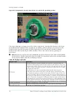
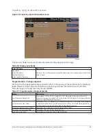
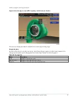
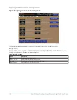
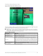
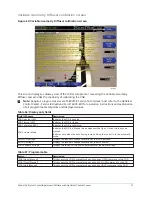
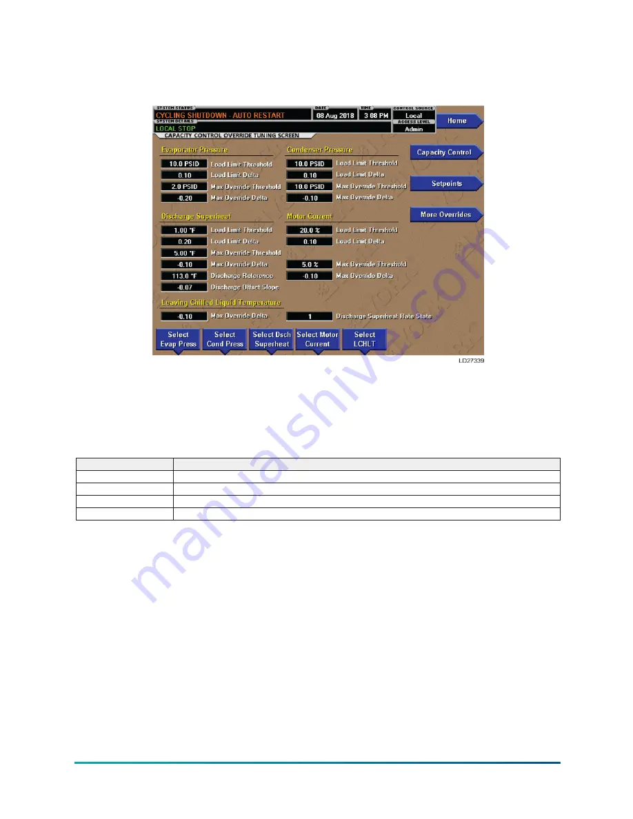
Capacity control override tuning screen

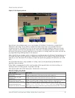
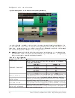
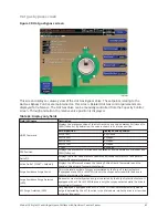
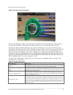
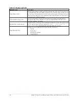
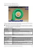
Figure 37: Capacity control override tuning screen

This screen shows parameters related to the Capacity Control Override Tuning logic.

Programmable

Access to this screen requires an Admin level password. Setpoints on this screen should only be

changed if directed by Product Technical Support.

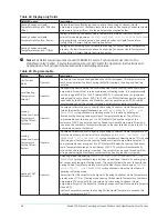
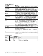
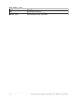
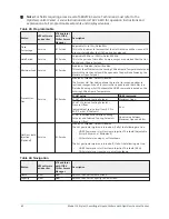
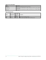
Table 40: Navigation

Button

Description

Home

Navigates to the Home screen.

Capacity Control

Navigates to the Capacity Control screen.

Setpoints

Navigates to the Capacity Control Setpoints screen.

More Overrides

Toggles the set of overrides displayed.

Model YK Style H Centrifugal Liquid Chillers with OptiView Control Center

58

Содержание YK Style H

Страница 1: ...160 76 O2 721 Operations Manual Issue Date 2021 08 13 Model YK Style H Centrifugal Liquid Chillers with OptiView Control Center With R 134a or R 513A Refrigerant for Electromechanical Starter Solid St...

Страница 2: ...2 Model YK Style H Centrifugal Liquid Chillers with OptiView Control Center...

Страница 3: ...ystem screen 31 Evaporator screen 33 Condenser screen 36 Heat recovery head pressure control screen 39 Head pressure control screen 43 Heat pump screen 45 Refrigerant level control screen 48 Compresso...

Страница 4: ...ntenance screen 123 Serial SD screen 125 Quick start screen 127 Schedule screen 131 User screen 133 Comms screen 135 Printer screen 137 Sales order screen 139 Operations screen 141 History screen 143...

Страница 5: ...te Starter safety shutdown messages 191 Compressor motor variable speed drive safety shutdown messages 192 Printing 195 Printing overview 195 Acceptable printers 196 Printer setup 197 Control center s...

Страница 6: ...6 Model YK Style H Centrifugal Liquid Chillers with OptiView Control Center...

Страница 7: ...that these individuals possess independent training that will enable them to perform their assigned tasks properly and safely It is essential that prior to performing any task on this equipment this...

Страница 8: ...l Only authorized personnel should be granted physical or logical access to the zone panel and Access Manager interface Mechanical keys to the control panel must be stored in a secure location To repo...

Страница 9: ...death to people at the site Note For more details see section beginning with YORK Chiller Access Manager for software version V10 and later Changeability of this document In complying with Johnson Con...

Страница 10: ...h OptiView Control Center and Remote Medium Voltage SSS 160 76 PW2 Wiring Diagram Field Connections for YK Chiller Style H with OptiView Control Center and Remote Medium Voltage VSD 160 76 PW3 Wiring...

Страница 11: ...d advance rules based rationale delivered by the Johnson Controls Connected Equipment Portal Nomenclature Refer to YK Engineering Guide Form 160 76 EG1 for Shell Motor Compressor combinations 11 Model...

Страница 12: ...ng the keys as labeled on the Control Center The chiller with the OptiView Control Center is applied with an Electromechanical Starter YORK Solid State Starter optional or Variable Speed Drive optiona...

Страница 13: ...ndle the refrigerant which would be evaporated at full load design conditions However most systems will be called upon to deliver full load capacity for only a relatively small part of the time the un...

Страница 14: ...Refrigerant flow through chiller falling film evaporator Figure 4 Refrigerant flow through chiller Model YK Style H Centrifugal Liquid Chillers with OptiView Control Center 14...

Страница 15: ...able setpoints and manual control shown in this manual that are for Service Technician use only They are only displayed when logged in at SERVICE access level or higher The setpoints and parameters di...

Страница 16: ...rcial chiller OPT Used on Microboard 031 03630 000 01 YK chiller xx controls revision level 00 01 etc y language package 0 equals English only 1 equals NEMA 2 equals CE 3 equals NEMA CE zz language pa...

Страница 17: ...instructing the user to press the ENTER button to stop the chiller or the CANCEL button to abort the stop command The Soft Stop command will drive the PRV closed and then shut off the chiller The Sta...

Страница 18: ...ints on the system the user must first log on with the appropriate access level Each of the programmable values requires a specific access level which is indicated beside the specified value All of th...

Страница 19: ...the highest access level Users logged on under higher access levels may perform any actions permitted by lower access levels Correct procedure requires that after making necessary setpoint adjustments...

Страница 20: ...arch bar or select a chiller from the list Figure 7 Selecting a chiller 4 On the chiller asset page click on the chiller Figure 8 Chiller asset page 5 Click Access Codes in the lower left area of the...

Страница 21: ...ar right Figure 10 List of access codes 7 If your name is not displayed click Add search for your name and click Generate code Figure 11 Adding a name 8 Select the start date for your code and the acc...

Страница 22: ...YORK Chiller Access Manager app 1 Log on to the YORK Chiller Access Manager app Figure 14 YORK Chiller Access Manager app 2 Tap the Add icon in the lower right corner of the screen Figure 15 Adding a...

Страница 23: ...16 Scanning QR code 4 On the Chiller Details screen tap Generate Access Code Figure 17 Chiller details 5 Select a start date if not today s date and tap Generate Access Code Figure 18 Generating acce...

Страница 24: ...anel with YORK Chiller Access Manager 1 To log on to the OptiView panel press the Login button on the Home screen Figure 20 Home screen 2 On the Login screen press the Login button Figure 21 Login scr...

Страница 25: ...er limits of the programmable range and the default value 2 If the dialog box begins with the word ENTER use the numeric keys to enter the desired value Leading zeroes are not necessary If a decimal p...

Страница 26: ...context multiple screens have been designed to describe the chiller operation In order to move from one screen to the next navigation keys have been defined These keys allow the user to either move F...

Страница 27: ...denser Liquid Temperature 19 97 133 9 F 28 9 56 6 C Entering Condenser Liquid Temperature 8 0 133 5 F 13 3 56 3 C Evaporator Refrigerant Temperature Optional 0 0 126 1 F 17 7 52 3 C Discharge Temperat...

Страница 28: ...W Available only if the chiller system is utilizing a Variable Speed Drive VSD Medium Voltage Variable Speed Drive MV VSD Mod B Solid State Starter or Medium Voltage Solid State Starter motor controll...

Страница 29: ...ars the fault and message when the condition has been removed The button only shows if the condition can be cleared If the chiller has a standing local or remote run command it starts when the button...

Страница 30: ...Motor Navigates to the VSD screen where Current Limit and the Pulldown Demand Limit values can be programmed Setpoints Navigates to the Setpoints screen which provides a single location to program th...

Страница 31: ...oint to which the Heat Pump is controlling the Leaving Condenser Liquid Temperature Only displayed when Heat Pump is enabled on the SETUP Screen and the Operation mode is set to Heating mode on the HE...

Страница 32: ...VDC 1 to 11 second PWM signal communicated through an SC EQ interface in BAS mode or a locally programmed value when in Local mode of operation Heating Condenser Liquid Temperature Leaving Displays t...

Страница 33: ...etween the Leaving Chilled Liquid temperature and the Evaporator Refrigerant Temperature The Evaporator Refrigerant Temperature will be represented by the Refrigerant Temperature sensor input if the s...

Страница 34: ...F A remote device can provide an analog signal 4 mA to 20 mA 0 VDC to 10 VDC or a 1 to 11 second PWM signal that changes the setpoint scaled by the user defined Minimum and Maximum values Additionally...

Страница 35: ...iption Home View View Returns the user to Home Screen Heat Pump View View Moves to a subscreen where you can program and view the Heat Pump Setpoints and parameters It only appears when Heat Pump is e...

Страница 36: ...ing the Leaving Condenser Liquid Temperature Only displayed when Heat Pump is enabled on the SETUP Screen and the Operation mode is set to Heating mode on the HEAT PUMP Screen Entering Condenser Liqui...

Страница 37: ...ondenser Condenser Liquid Pump Run Stop Indicates whether condenser liquid pump is operating Condenser Refrigerant Level Displays the present position of the refrigerant level if this function is enab...

Страница 38: ...f the Heat Recovery setpoints and parameters Only appears when the Heat Recovery is enabled Head Pressure Control Service JCI Service Moves to a sub screen allowing programming and viewing of the Head...

Страница 39: ...ly with Heat Pump Duty When Heat Pump Duty is enabled Heat Recovery is automatically disabled and locked When Heat recovery is enabled the condenser flow animation will show flow when either the Conde...

Страница 40: ...rol and both are enabled there is not a control valve for each feature Rather there is one common valve that is either performing Hot Water Control for Heat Recovery or it is performing Head Pressure...

Страница 41: ...abled Control Valve Output Settings PID Output Direct or Reverse Allows the output signal to the Control Valve to be set to direct or reverse acting When set to direct the voltage or current signal to...

Страница 42: ...fault 2 00 Use the Change Setpoints key as described above to select enter this setpoint Appears when Head Pressure Control is enabled Head Pressure Control D Sets the Derivative Gain of the Head Pres...

Страница 43: ...Pressure Control feature is contained in OptiView Control Center Service Instructions Form 160 76 M1 Note Requires a login access level of SERVICE Service Technicians must refer to the OptiView Contr...

Страница 44: ...irect or reverse acting When set to direct the voltage or current signal to the Control Valve is at minimum for a 0 command and at maximum for a 100 command When set to reverse the voltage or current...

Страница 45: ...isabled when Heating mode is selected If the chiller is equipped with a VSD it will operate at full speed 50 Hz or 60 Hz at all times in Heating mode In Cooling mode it operates normally All setpoints...

Страница 46: ...the user to specify the Leaving Condenser Liquid Temperature at which the Heat Pump will shutdown on LEAVING CONDENSER LIQUID HIGH TEMPERATURE cycling shutdown in Heating mode This is done by definin...

Страница 47: ...YORK Chiller Access Manager Description Home View View Returns the user to Home screen Evaporator View View Returns user to Evaporator screen Condenser View View Returns user to Condenser screen 47 Mo...

Страница 48: ...rigerant level is animated in the cutaway view of the condenser Actual level Displayed level 0 to 15 50 16 to 31 60 32 to 47 70 48 to 63 80 64 to 79 90 79 100 Subcooler Effectiveness The Subcooler Eff...

Страница 49: ...Valve Command by an amount equal to the Manual Increment with a maximum of 100 0 Close Pressing this button will set the Condenser Level Control Valve Mode to Manual if it had been in Auto and will d...

Страница 50: ...uto zeroing during the System Prelube If either of the transducers used to calculate this differential is out of range the display field shows XX X The offset pressure is the pressure differential bet...

Страница 51: ...Indicates the amount of error between the PRV setpoint and feedback Shown in Admin level only Motor Run LED Illuminates when the compressor motor is running Table 31 Programmable Button Description PR...

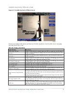
Страница 52: ...sure setpoint above which the high condenser pressure capacity control override takes effect Adjusted Superheat Displays the superheat temperature Adjusted Superheat Override Threshold Displays the su...

Страница 53: ...Pressure Override is in control Evaporator Pressure Evaporator Pressure Override is in control Low LCHLT LCHLT low temperature Override is in control Discharge Superheat Low Discharge Superheat Overri...

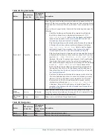
Страница 54: ...time the button is pressed Decrease Service JCI Service Pressing this button will set the selected device s state to Manual if it had been in Auto and will decrease the device s present control comman...

Страница 55: ...VICE Table 37 Programmable change setpoints Button Description LCHLT Setpoint Ramp Rate Adjustable 0 1 F S to 2 0 F S Default 0 1 F S When the chiller starts the LCHLT Setpoint is ramped from the LCHL...

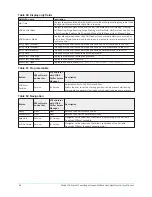
Страница 56: ...tion Home Navigates to the Home Screen Capacity Control Navigates to the Capacity Control Screen Anti Surge Tuning Navigates to the Anti Surge Tuning Screen Model YK Style H Centrifugal Liquid Chiller...

Страница 57: ...l but all of the settings require an Admin level password to change and should only be changed when directed by Product Technical Support Table 39 Navigation Button Description Home Navigates to the H...

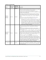
Страница 58: ...level password Setpoints on this screen should only be changed if directed by Product Technical Support Table 40 Navigation Button Description Home Navigates to the Home screen Capacity Control Naviga...

Страница 59: ...Speed Thrust Bearing Proximity Reference Position Displays the presently defined offset reference position This value is defined at the conclusion of a calibration sequence Oil Pressure Displays the...

Страница 60: ...o cancel calibration Accept Calibration Press this key to accept calibration Fault Acknowledge This option is only displayed if a fault is present Allows clearing of High Speed Thrust Bearing related...

Страница 61: ...en 0 closed and 100 full open Delta P P Displays the chiller head pressure calculated as condenser pressure evaporator pressure evaporator pressure Active Delta T LCHLT Setpoint Displays the differenc...

Страница 62: ...o respond quicker to fast load changes When Process Hot Gas is enable and the chiller is in Prelube Running or Soft Shutdown the HGBP command is based on the Entering Chilled Liquid Temperature ECHLT...

Страница 63: ...ed below Table 47 Display only fields Field LED name Description Delta P P A parameter that represents the system differential or Head Pressure It is calculated as condenser pressure evaporator pressu...

Страница 64: ...ount This is the total number of surges accumulated by the Surge Protection feature If equipped with a VSD or MV VSD it is only the surges detected while the drive is running at maximum frequency Exte...

Страница 65: ...rection avoidance Extended Run mode This is implemented when an Excess Surge situation is detected as follows Anytime the Surge Window Count exceeds the Count Limit the Pre rotation Vanes are driven c...

Страница 66: ...e Surge Window Count is less than or equal to the Count Limit this message and load inhibit are automatically cleared Alternating with this message is WARNING EXCESS SURGE DETECTED that continues afte...

Страница 67: ...VGD VGD Closing LED Illuminates when a close signal is being applied to the VGD VGD Position Shows the position of the VGD 0 to 100 open Maximum VGD Position Shows the maximum calculated value that th...

Страница 68: ...D Auto This key puts the VGD into automatic control mode Pressures Discharge Display the compressor discharge pressure Pressures Condenser Display the condenser pressure Pressures Head Display the hea...

Страница 69: ...t voltage decreases to this level The minimum difference between the High Limit Setpoint and the Low Limit Setpoint is 0 1 VDC If a Low Limit Setpoint is entered which is less than 0 1 VDC below the H...

Страница 70: ...stall conditions are not checked the VGD control is inhibited and the VGD is pulsed open according to the Open Pulse Setpoint While this is in effect PRV Position Override is displayed as Control Stat...

Страница 71: ...LED Indicates the VGD is calibrated VGD Actuator Mode Indicates the VGD is in Manual mode whenever the Open Close or Hold keys are pressed Indicates Auto when the Auto key is pressed putting the contr...

Страница 72: ...Pressed during the VGD calibration routine to indicate that the VGD is physically at the 0 position Table 58 Navigation Button V09 software and earlier V10 and later with YORK Chiller Access Manager...

Страница 73: ...manual buttons are pressed at Service level Displays Auto when the Auto key is pressed to return to automatic PRV position control Calibration in Progress LED Indicates the calibration routine is in p...

Страница 74: ...lier V10 and later with YORK Chiller Access Manager Description Home View View Returns the user to Home Screen Compressor View View Returns the user to Compressor Screen Model YK Style H Centrifugal L...

Страница 75: ...between 0 closed and 100 full open Delta P P Displays the chiller head pressure calculated as condenser pressure evaporator pressure evaporator pressure Temperature Differential LCHLT Setpoint Displa...

Страница 76: ...to manual mode Each time it is pressed it lowers the Command Frequency to the drive by the amount defined by the MANUAL INCREMENT key It will not lower the value below the minimum allowed 30 Hz for 60...

Страница 77: ...ted Condenser Temperature This parameter is useful when analyzing oil heater operation since it is used in the control of the oil heater Target Oil Temperature Displays the desired oil temperature set...

Страница 78: ...key allows the user to specify a fixed manual speed at which the VSOP will run Auto Service JCI Service This key returns the VSOP to automatic mode where control is based on the Oil Pressure Setpoint...

Страница 79: ...vice JCI Service Allows the user to enable or disable the standby lube operation When enabled this function causes the oil pump to operate for a period of two minutes at 24 hour intervals from when th...

Страница 80: ...ta returned by the CM 2 board Current Limit Setpoint Displays the current limit value in use This value could come from a 4 mA to 20 mA 0 VDC to 10 VDC PWM signal or SC EQ communication interface or a...

Страница 81: ...t up Pulldown Demand Time Operator Standard Allows the user to set a period of time for which the pulldown demand limit will be in effect after the chiller starts Table 70 Navigation Button V09 softwa...

Страница 82: ...ldown period Input Power Displays the kilowatts measured by the Solid State Starter KW Hours Displays the cumulative amount of kilowatts used over time Starter Model Displays the Solid State Starter m...

Страница 83: ...ange for voltage checking When not disabled this line voltage range is used to determine a low line and high line volt age threshold for initiating a shutdown Starting Current Service JCI Service Defi...

Страница 84: ...Input Power Displays the kilowatts measured by and transmitted from the starter KW Hours Displays the cumulative kilowatt hours The microboard calculates this value from the Input Power transmitted fr...

Страница 85: ...ndard Allows the user to set the period of time for which the pulldown demand limit will be in effect Full Load Amps Service JCI Service Defines the maximum amps at which the motor can operate This va...

Страница 86: ...nt output frequency to the motor Input Power Displays the total kilowatts measured by the VSD or Harmonic Filter if installed KW Hours Displays the cumulative amount of kilowatts used over time as the...

Страница 87: ...tive Kilowatt hours to zero 0 Filter Inhibit Harmonic Filter installed Only Service JCI Service Disable the filter logic from activating although the system will still communicate with the device Only...

Страница 88: ...Input Power Displays the total kilowatts measured by the VSD Input kW Hours Displays the cumulative amount of kilowatts used over time as the VSD motor controller operates Voltage Total Harmonic Dist...

Страница 89: ...re rotation vanes will not be permitted to open further If the input current rises above this value the pre rotation vanes will close to reduce the current to this value Pulldown Demand Limit Operator...

Страница 90: ...is not zero Output Voltage Displays the output voltage to the motor Value is provided by the MV VSD VSD Output Frequency Displays the present output frequency to the motor Value is provided by the MV...

Страница 91: ...This value is the maximum drive frequency Hz when the MV VSD receives a 100 speed command from the OptiView Control Center If the value received is not 50 Hz or 60 Hz INVALID is displayed If this is...

Страница 92: ...he pulldown demand limit will be in effect after the chiller starts Full Load Amps Service JCI Service Defines the maximum amps at which the motor can operate this value is viewable when logged in at...

Страница 93: ...a 0 mA to 20 mA 0 VDC to 10 VDC PWM signal or SC EQ communication interface or a locally programmed value Motor Run LED Illuminated when the Control Center is commanding the drive to run Otherwise it...

Страница 94: ...mp up will begin Programmable over the following range 0 Hz to 210 Hz default 45 Hz Mapping Enable Sets the Delta T Leaving Chilled Liquid Temperature Setpoint needed to be met to enable surge mapping...

Страница 95: ...screen under Selected The default position for the green box is in the upper left corner of the view window Once moved it will remain at the last position The Present Operating conditions are indicat...

Страница 96: ...lta P P of the selected surge point Present Displays the present Delta P P Note For fields requiring access level of SERVICE Service Technicians refer to the OptiView Control Center Service Instructio...

Страница 97: ...ext list of parameters This screen is applicable to Variable Speed Drives VSD and Medium Voltage Variable Speed Drives MV VSD Note Requires a login access level of SERVICE Service Technicians refer to...

Страница 98: ...Description Home Returns user to HOME Screen Capacity Control Returns user to Capacity Control Screen ACC Details Returns user to ACC DETAILS Screen Model YK Style H Centrifugal Liquid Chillers with...

Страница 99: ...programmed pulldown period if the value is nonzero Operating Mode Run Stop Indicates whether the Harmonic Filter is operating VSD Model Displays the horsepower for which the attached Harmonic Filter...

Страница 100: ...he user to specify the maximum allowed motor current as a percentage of FLA When the motor current reaches this value the pre rotation vanes will not be permitted to open further If the motor current...

Страница 101: ...esponse a safety shutdown Motor Lack of Bearing Lubrication is performed when the operating hours since the last lubrication exceed the Motor Lube Required period plus 200 hours See Display messages o...

Страница 102: ...to the OptiView Control Center Service Instructions Form 160 76 M1 for operation instructions and explanation of all programmable setpoints and displayed values Table 99 Programmable Button V09 softwa...

Страница 103: ...owing procedure The entry must be a minimum of 3 characters and a maximum of 8 characters At the keypad log in at Operator access level using password 9 6 7 5 If resetting the safety shutdown Motor La...

Страница 104: ...eline routine that plots a baseline over a 1 hour period while the chiller is running This screen also serves as a gateway to a subscreen that allows programming of the winding High Temperature Warnin...

Страница 105: ...lid and displays as XXX X Average Winding Temperature This value is calculated as the average of all enabled and valid Motor Winding Temperatures Any winding temperature that registers as open out of...

Страница 106: ...or lower limit Shaft End High Vibration Warning Shaft End Vibration Baseline X2 Shaft End High Vibration Warning Default Shaft End Vibration Baseline X2 Opposite Shaft End High Vibration Warning Oppos...

Страница 107: ...tor winding temperatures as reported by the winding transmitters by the motor monitoring board serial communications VSD transmitter Enables and displays the 3 motor winding temperatures as reported b...

Страница 108: ...tection feature The status LED and text do not appear The Motor Cooling Coil Leak fault will not occur This setting is used when the motor is not equipped with a leak detector or if it is desired to d...

Страница 109: ...Description Home View View Returns the user to Home screen Motor View View Returns the user to Motor screen Setpoints Service JCI Service Moves to a subscreen allowing programming of additional motor...

Страница 110: ...able setpoint key can be used to enable or disable individual winding temperature sensors Not shown when Winding Temperature Protection Setpoint on the Motor Details screen is set to Disabled High Win...

Страница 111: ...Setpoints see Vibration Setup in the Programmable section Also displayed is the Delay which is the amount of time the vibration must exceed the warning threshold before the warning is displayed Vibra...

Страница 112: ...aseline derived values The active threshold values are displayed in the Motor Bearings High Vibration Shutdown and High Vibration Warning data boxes on this screen The Vibration Baseline values from w...

Страница 113: ...t on Motor Details screen is set to Disabled Allows a Service Technician to enter values for High Bearing Temperature Shutdown 149 F to 212 F default 203 F and Warning 140 F to 194 F default 194 F thr...

Страница 114: ...alue is calculated by subtracting the Leaving Chilled Liquid Temperature Cycling Offset Shutdown from the Leaving Chilled Liquid Temperature Setpoint If this value is below the absolute minimum allowe...

Страница 115: ...etpoint to a maximum restart value of 82 F The chiller will automatically restart when this temperature is reached This setpoint can be used to reduce chiller cycling by delaying the chiller restart u...

Страница 116: ...cate the status of the Run commands from the three possible sources and the Active Run Command status The selected Run Stop Control Source is displayed Motor Current Limit Control Displays the Active...

Страница 117: ...selected Minimum min signal Refer to Form 160 76 PW4 for more details on the BAS interfaces Select Current Limit Operator Standard Allows the user to select the Control Source for Current Limiting Lo...

Страница 118: ...l Center Service Instructions Form 160 76 M1 establishes this configuration per the desired operation This screen also serves as a gateway to more subscreens for defining general system parameters Tab...

Страница 119: ...his key places a green selection box around the first changeable setpoint The access level determines which setpoints can be changed Use the and keys to place the selection box around the desired setp...

Страница 120: ...ian to enable or disable Variable Water Outlet Control to meet European CE requirements When Variable Water Outlet Control is Enabled on the Setup Screen the local and remote cooling setpoints are ign...

Страница 121: ...the respective device Table 120 Programmable Button Description Default Unit Setpoints Many of the control parameters are automatically configured by pressing this button after the Sales Order screen...

Страница 122: ...otor Monitoring Board screen I O Board Navigates to the I O Board screen to allow the Service Technician to view the expansion i o board analog and digital status and also the Modbus communication err...

Страница 123: ...able 123 Programmable Button Access level Description Condenser Small Temperature Difference Warning Threshold Service level and above Displays the condenser small temperature difference warning thres...

Страница 124: ...enter code 0726 Condenser High Small Temp Difference Warning Test Op Allows you to enable or disable the Condenser High Small Temperature Difference feature A service warning appears as yellow in the...

Страница 125: ...Order Number Chiller Serial Number Displays the chiller order and serial number Table 126 Programmable Button Description Data Logging Enabled or Disabled Default Disabled Logging Interval Adjustable...

Страница 126: ...lowing limited diagnostic capability while operating System Backup Jumps to the System Backup screen to save the chiller system files System Restore Jumps to the System Restore screen to write the sav...

Страница 127: ...start If the conditions for a Quick Restart are not met the next time the chiller is started it has a prelube period just like a normal start however the vanes will begin to open at the beginning of...

Страница 128: ...nter key A dialog box appears with the range of settings VSD Start Frequency Service JCI Service The VSD Start Frequency is as follows 60 Hz units with quick start enabled equal 30 Hz to 45 Hz default...

Страница 129: ...form of an offset above the active Leaving Chilled Liquid Temperature LCHLT Setpoint Once the Leaving Chilled Liquid Temperature falls below the Active LCHLT Setpoint plus Quick Pulldown Setpoint Off...

Страница 130: ...and later with YORK Chiller Access Manager Description Home Service JCI Service Returns the user to Home screen Setpoints Service JCI Service Returns the user to Setpoints screen Model YK Style H Cent...

Страница 131: ...erate continuously through several days the Stop time of Day 1 can be set to 11 59 PM and the Start time of Day 2 can be set to 12 00 AM The chiller will not stop but continue to operate until the sto...

Страница 132: ...the Standard week definition as described above Schedule Enabled Disabled Operator Standard Allows the user to enable or disable the monitoring function which enforces the scheduled starting and stopp...

Страница 133: ...hich enables the cursor arrows which are used to highlight the custom user parameter the user wishes to modify At this point the Enter button is pressed and the value may be entered Display only field...

Страница 134: ...Service This allows the user to specify up to four custom User ID values Each User ID will then require a corresponding password and user level A User ID can be defined for various maintenance personn...

Страница 135: ...ers This ID number is also printed at the top of reports obtained with a local printer Printer Setup Operator Standard Pressing either key places a green selection box around the first changeable para...

Страница 136: ...ta bits with which the panel communicates to the modem port COM 2 Parity Bits Operator Standard Defines the number of parity bits with which the panel communicates through the modem port COM 2 Stop Bi...

Страница 137: ...138 Programmable Button V09 software and earlier V10 and later with YORK Chiller Access Manager Description Automatic Printer Logging Operator Standard Enables or disables automatic printer logging Lo...

Страница 138: ...s report present value of the system setpoints Schedule report present value of the system schedule times or a Sales Order Data report information provided on the Sales Order Screen A print report is...

Страница 139: ...ll of the information Table 140 Display only fields Field LED name Description Model Number Factory defined model number of the chiller system Panel Serial Number Factory defined serial number for the...

Страница 140: ...on Service JCI Service Factory entered job location that the chiller is destined for Print View View This generates a listing of the Sales Order data Table 142 Navigation Button V09 software and earli...

Страница 141: ...are and earlier V10 and later with YORK Chiller Access Manager Description Control Source Operator Standard Defines whether the control of the chiller will be Local Digital Remote Analog Remote Modem...

Страница 142: ...ntrols the chiller per the requirements of the entered chiller style and compressor Edit Phone Numbers Service JCI Service Displays up to two service phone numbers The Regional service phone number is...

Страница 143: ...This window displays the date and time and the description of the last normal shutdown A normal shutdown is defined as follows Local Soft Stop Button Remote Digital Analog or ISN Last Fault While Runn...

Страница 144: ...tion Home View View Returns the user to Home Screen View Details View View Navigates to a subscreen containing the value of select chiller parameters at the time of the associated shutdown Trending Vi...

Страница 145: ...requiring access level of SERVICE Service Technicians refer to the OptiView Control Center Service Instructions Form 160 76 M1 for operation instructions and explanation of all programmable setpoints...

Страница 146: ...rlier V10 and later with YORK Chiller Access Manager Description Home View View Returns the user to Home screen History View View Returns to the previous History screen Model YK Style H Centrifugal Li...

Страница 147: ...time of the change access level and User ID used to make the change the old setpoint value and the new setpoint value Note Requires a login access level of SERVICE Service Technicians refer to the Op...

Страница 148: ...p in the displayed data if applicable Page Down Service JCI Service Scrolls down in the displayed data if applicable Table 154 Navigation Button V09 software and earlier V10 and later with YORK Chille...

Страница 149: ...Displays the setpoint category that was changed Time Displays the time the setpoint was changed Date Displays the date the setpoint was changed Access Level Displays the login Access Level used to mak...

Страница 150: ...iew Control Center Service Instructions Form 160 76 M1 for operation instructions and explanation of all programmable setpoints and displayed values Table 158 Programmable Button V09 software and earl...

Страница 151: ...down through list of available parameters Select First use the page up and page down keys to scroll through the Slot Numbers list and note the number of the parameter s to be displayed Pressing the Se...

Страница 152: ...r V10 and later with YORK Chiller Access Manager Description Home View View Returns the user to Home screen Custom View Service JCI Service Returns to the Custom View screen Model YK Style H Centrifug...

Страница 153: ...X Axis If the actual value of the sampled parameter is less than the Y Axis label minimum for that parameter the value will be plotted at the minimum value Similarly if the actual value is greater tha...

Страница 154: ...egin immediately Stop Operator Standard Pressing this key stops the trending The trend data is frozen on the display until another graph is started with the Start key The Stop key is only available if...

Страница 155: ...are entered as Data Point Min and Data Point Max for Data Points 1 through 6 The interval at which all the parameters are sampled is selected as the Data Collection Interval Display only fields None N...

Страница 156: ...be sampled every 900 seconds with the last 112 5 hours 4 7 days of data viewable on the screen Therefore the selected interval is a compromise between resolution and full screen time display Select t...

Страница 157: ...This is the maximum value displayed for the Y axis Selecting a parameter for a Data Point sets this to the default value which is the highest value allowed for that parameter It can be changed to a v...

Страница 158: ...ata collection is started or stopped after any selected trigger delay per the selected Trigger Action A Secondary Trigger can be evaluated with the Primary Trigger to start stop data collection The Pr...

Страница 159: ...lay is selectable from 1 to 864 000 seconds 10 days Display is in days hours minutes and seconds The delay timer begins when the triggers evaluate as true If the Trigger Action is set to Start data co...

Страница 160: ...lot Numbers of the most commonly used parameters Note For fields requiring access level of SERVICE Service Technicians refer to the OptiView Control Center Service Instructions Form 160 76 M1 for oper...

Страница 161: ...arlier V10 and later with YORK Chiller Access Manager Description Home View View Returns the user to Home screen Trend Setup View View Returns to the Trend Setup screen 161 Model YK Style H Centrifuga...

Страница 162: ...tput Voltage 291 Jumper Power Failure Restart 2824 VSD Phase A Current 292 Jumper Pre Run Operation 2825 VSD Phase B Current 293 Jumper Refrigerant Selection 2826 VSD Phase C Current 294 Jumper VSD Mo...

Страница 163: ...lter L1 N Peak Voltage 1811 Evaporator Is Refrigerant Sensor Present 2876 Filter L2 N Peak Voltage 1812 Evaporator Refrigerant Temperature 2877 Filter L3 N Peak Voltage 1813 Evaporator Delta P P 2878...

Страница 164: ...evel Is Pulldown In Effect 2317 Motor Current Limit Remote Digital Setpoint 8211 Refrigerant Level Pulldown Time Remaining 2351 Motor Operating Hours Since last Lubrication 8212 Refrigerant Level Targ...

Страница 165: ...own but will start upon receipt of a local or remote start signal Cycling Shutdown Auto Restart The chiller is shut down on a cycling shutdown The cause of the shutdown is still in effect and is displ...

Страница 166: ...whichever occurs first the Run Signal is removed from the compressor motor starter and a System Coastdown is performed Soft Shutdowns are initiated by the following 1 Leaving Chilled Liquid Low tempe...

Страница 167: ...t thresholds are elevated See the following table Table 174 Motor Current Motor current FLA Vane control Electro mechanical Solid State Starter VSD Service mode On rise inhibit open 100 100 107 On fal...

Страница 168: ...Pressure A minimum of 15 PSID of oil pressure was not achieved in the first 30 seconds of a Standby Lubrication cycle or the pressure decreased below this value during the remainder of the cycle This...

Страница 169: ...Motor Variable Speed Drive VSD Logic Board or the Adaptive Capacity Control Board is not occurring While this condition exists all filter related parameters are displayed as X s This message automati...

Страница 170: ...er was running This feature verifies the operation of the Stall transducer and the Condenser transducer Since both transducers are measuring essentially the same pressure both outputs should be within...

Страница 171: ...or higher using the MOTOR LUBE ACKNOWLEDGE key on the MOTOR LUBRICATION Screen See the Motor lubrication screen for entry instructions The date and time of this entry is automatically logged as the D...

Страница 172: ...cations If the chiller is running when this occurs the Pre rotation Vanes are driven fully closed prior to shutting down the chiller Local Stop A local shutdown command has been initiated by the Opera...

Страница 173: ...structions in OptiView Control Center Service Instructions Form 160 76 M1 Leaving Chilled Liquid Low Temperature The Leaving Chilled Liquid Temperature has decreased to the programmed Shutdown Tempera...

Страница 174: ...ble 176 CM 2 faults Device Manual reset fault Automatic reset fault Overload None CM 2 Module Overload Phase Rotation Loss Motor Controller Loss Of Current The Compressor Motor current decreased to 10...

Страница 175: ...enter after 10 consecutive attempts to communicate with the Control Center after Initialization has been successfully completed The Control Center attempts to establish communications until successful...

Страница 176: ...ermitted to start when the jumpers are configured correctly Refer to Solid State Starter Mod B Operation and Maintenance Form 160 00 O2 for valid jumper configurations LCSSS Phase Locked Loop The Liqu...

Страница 177: ...cycling shutdown messages The following cycling shutdown messages are displayed on Compressor Motor Variable Speed Drive VSD applications only These messages are generated by events that occur within...

Страница 178: ...c Board s LED s alternately blinking The filter can be eliminated as a cause of initialization failure by disconnecting the filter by placing switch SW1 on the Filter Logic Board in the OFF position a...

Страница 179: ...necessary to look at the level of the 460 VAC applied to the drive The specified voltage range is 414 to 508 VAC If the incoming voltage is in excess of 508 VAC steps should be taken to reduce the vol...

Страница 180: ...ause the strainer to plug Locations with special conditions may want to consider a dual strainer arrangement with quarter turn valves to permit cleaning of one strainer with the unit still on line Plu...

Страница 181: ...e Low DC Bus Voltage During pre charge the DC link must be equal to or greater than 50 VDC 41 VDC for 50 Hz within second and 500 VDC within 15 seconds after the pre charge relay is energized If this...

Страница 182: ...instantaneous Harmonic Filter current is monitored and compared to a preset limit If this limit is exceeded a shutdown is performed and this message is generated The filter current is monitored using...

Страница 183: ...DC capability for the DC link It is important the voltage is shared equally from the junction of the center or series capacitor connection to the negative bus and to the positive bus This center point...

Страница 184: ...Water Cooling R 134a 25 0 25 1 Brine Cooling R 513A 9 0 to 29 0 as programmed 0 1 more than Shutdown threshold Brine Cooling R 134a 6 0 to 25 0 as programmed 0 1 more than Shutdown threshold Evaporato...

Страница 185: ...res this value to the optional Evaporator Refrigerant Temperature Sensor If the difference between these temperatures is greater than 3 0 F continuously for 1 minute this shutdown is performed This ch...

Страница 186: ...efined safety shutdown input The chiller can be started after the contacts open and the Clear Fault key is pressed on the display Discharge High Temperature The discharge temperature as sensed by the...

Страница 187: ...sing the same pressure during this period and their outputs should be similar The chiller can be started after the Clear Fault key is pressed on the display Oil Variable Speed Pump Setpoint Not Achiev...

Страница 188: ...r when the actual clearance is less than 22 mils The clearance is only checked during the last 20 seconds of System Prelube during System Run and during coastdown Therefore the fault is only detected...

Страница 189: ...safety shutdown and re initialization of the program This is generally indicative of a severe electrical power disturbance or impending Microboard Failure The chiller can be started after the Clear F...

Страница 190: ...this safety threshold is displayed as High Bearing Temperature Shutdown on the MOTOR SETPOINTS Screen It is programmed with the Bearing Setup Setpoint on that screen The chiller can be started after...

Страница 191: ...ture is less than 109 F LCSSS 105 Motor Current Overload The highest phase of the compressor motor current increased to greater than 105 of the programmed 100 chiller Full Load Amps continuously for 4...

Страница 192: ...utdown is generated by the VSD Logic Board and it indicates that a motor overload has occurred The shutdown is generated when the VSD Logic Board has detected that at least 1 of the 3 output phase cur...

Страница 193: ...C Inverter Baseplate Temperature VSD part number 371 03789 xxx 503HP 60 Hz 419HP 50 Hz The chiller has shutdown because the baseplate temperature has increased to greater than 158 F The chiller can b...

Страница 194: ...ent to the VSD Filter is not sinusoidal This shutdown will occur if the TDD exceeds 25 continuously for 45 seconds TDD is an acronym for Total Demand Distortion a term defined by the IEEE Std 519 1992...

Страница 195: ...of shutdown Automatically occurs if printer is connected at time of shutdown Adaptive Capacity Control ACC Surge Map System conditions at instant all surge points were mapped Compressor Motor Variable...

Страница 196: ...onnected to the Control Center However the print format may not be correct or as desired Proceed with caution and use the following guidelines if an unlisted printer is selected 1 All must be capable...

Страница 197: ...n the following table Table 182 Brecknell CP130 Microboard Printer Function J2 4 Pin 3 TX Data to the printer J2 2 Pin 5 Busy signal from the printer J2 9 Pin 6 Signal Common The following hardware is...

Страница 198: ...Value Baud Rate Set to 19200 Data Bits 8 Parity None Stop Bits 1 Printer type Operator Standard Using the Printer Screen set the printer type to Weigh Tronix Automatic data logging Operator Standard I...

Страница 199: ...s 1 Flow control None 4 Set HyperTerminal to capture a file a Select Transfer from toolbar b Select Capture Text from the drop down list c A Capture Text Filebox will be displayed Verify location and...

Страница 200: ...232 pin assignments DB9 PC signal set most laptops Pin Connection Pin 1 Received line Signal Detector Data Carrier Detect Pin 2 Recieved Data Pin 3 Transmit Data Pin 4 Data Terminal Ready Pin 5 Signa...

Страница 201: ...Sample printouts Figure 86 Sample printout status 201 Model YK Style H Centrifugal Liquid Chillers with OptiView Control Center...

Страница 202: ...Figure 87 Sample printout status cont Model YK Style H Centrifugal Liquid Chillers with OptiView Control Center 202...

Страница 203: ...Figure 88 Sample printout setpoints 203 Model YK Style H Centrifugal Liquid Chillers with OptiView Control Center...

Страница 204: ...Figure 89 Sample printout setpoints cont Model YK Style H Centrifugal Liquid Chillers with OptiView Control Center 204...

Страница 205: ...Figure 90 Sample printout schedule 205 Model YK Style H Centrifugal Liquid Chillers with OptiView Control Center...

Страница 206: ...Figure 91 Sample printout sales order Model YK Style H Centrifugal Liquid Chillers with OptiView Control Center 206...

Страница 207: ...Figure 92 Sample printout sales order cont 207 Model YK Style H Centrifugal Liquid Chillers with OptiView Control Center...

Страница 208: ...Figure 93 Sample printout history Model YK Style H Centrifugal Liquid Chillers with OptiView Control Center 208...

Страница 209: ...Figure 94 Sample printout history cont 209 Model YK Style H Centrifugal Liquid Chillers with OptiView Control Center...

Страница 210: ...Figure 95 Sample printout security log report Figure 96 Sample printout trend data new or existing points Model YK Style H Centrifugal Liquid Chillers with OptiView Control Center 210...

Страница 211: ...n report Figure 98 Sample printout adaptive capacity control new map point report Figure 99 Sample printout adaptive capacity control existing map points report 211 Model YK Style H Centrifugal Liquid...

Страница 212: ...ers mm Weight Pounds lbs 0 4536 Kilograms kg Velocity Feet Second fps 0 3048 Meters Second m s Feet of water ft 2 989 Kilopascals kPa Pressure drop Pounds Square Inch psi 6 895 Kilopascals kPa Tempera...

Отзывы: