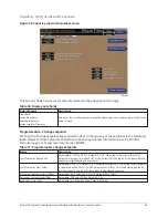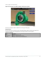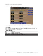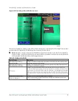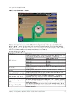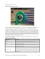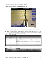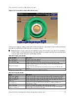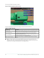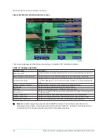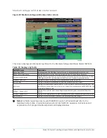
Variable Geometry Diffuser setpoints screen
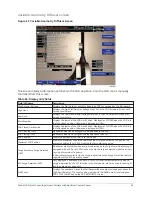
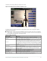
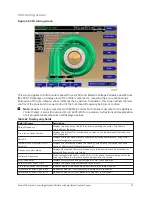
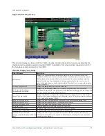
Figure 42: Variable Geometry Diffuser setpoints screen
The Variable Geometry Diffuser setpoints are maintained on this screen. All setpoints require a
login access level of Service.
Note:
Requires a login access level of SERVICE. Service Technicians must refer to the
OptiView
Control Center - Service Instructions (Form 160.76-M1)
for operation instructions and explanation
of all programmable setpoints and displayed values.
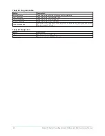
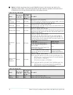
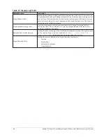
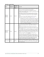
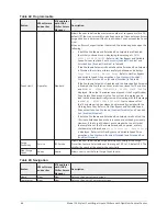
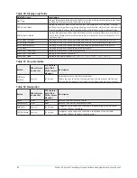
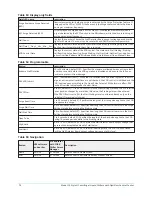
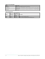
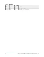
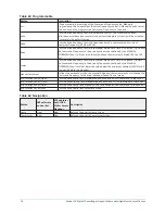
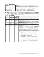
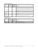
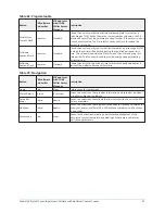
Table 53: Display only fields
Field/LED name
Description
Stall Detector Voltage
Displays the Stall Detector output voltage, as received by the Microboard.
High Limit
(0.5 to 1.2 VDC; default 0.6 VDC; Specifies the Stall Detector Board output voltage that
represents an acceptable amount of stall noise.
Low Limit
(0.4 to 0.8 VDC; default 0.5 VDC; In the Stall Reacting State, the VGD is driven closed
until the Stall Detector Board output voltage decreases to this level. The minimum
difference between the High Limit Setpoint and the Low Limit Setpoint is 0.1 VDC. If a
Low Limit Setpoint is entered which is less than 0.1 VDC below the High Limit Setpoint,
the High Limit Setpoint is adjusted so that it is 0.1 VDC above the newly entered Low
Limit value.
Mach Number
Displays the compressor calculated mach number (gas flow velocity), based on drive
speed and suction conditions.
VGD Closed Limit Switch
Displays the status of the VGD Limit Switch. Displayed as CLOSED when the switch
is closed. This would be when the VGD is in the fully closed position. Otherwise,
displayed as OPEN.
VGD Opening (LED)
Illuminates when an open signal is being applied to the VGD.
VGD Closing (LED)
Illuminates when a close signal is being applied to the VGD.
VGD Position
Shows the position of the VGD. 0 to 100% open.
Maximum VGD Position
Shows the maximum calculated value that the VGD will be allowed to open for the
present condition. (0 to 100%). Opening too far could cause surge.
69
Model YK Style H Centrifugal Liquid Chillers with OptiView Control Center
Содержание YK Style H
Страница 2: ...2 Model YK Style H Centrifugal Liquid Chillers with OptiView Control Center...
Страница 6: ...6 Model YK Style H Centrifugal Liquid Chillers with OptiView Control Center...
Страница 202: ...Figure 87 Sample printout status cont Model YK Style H Centrifugal Liquid Chillers with OptiView Control Center 202...
Страница 203: ...Figure 88 Sample printout setpoints 203 Model YK Style H Centrifugal Liquid Chillers with OptiView Control Center...
Страница 204: ...Figure 89 Sample printout setpoints cont Model YK Style H Centrifugal Liquid Chillers with OptiView Control Center 204...
Страница 205: ...Figure 90 Sample printout schedule 205 Model YK Style H Centrifugal Liquid Chillers with OptiView Control Center...
Страница 206: ...Figure 91 Sample printout sales order Model YK Style H Centrifugal Liquid Chillers with OptiView Control Center 206...
Страница 207: ...Figure 92 Sample printout sales order cont 207 Model YK Style H Centrifugal Liquid Chillers with OptiView Control Center...
Страница 208: ...Figure 93 Sample printout history Model YK Style H Centrifugal Liquid Chillers with OptiView Control Center 208...
Страница 209: ...Figure 94 Sample printout history cont 209 Model YK Style H Centrifugal Liquid Chillers with OptiView Control Center...

