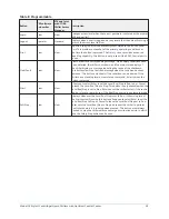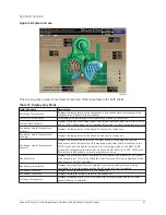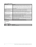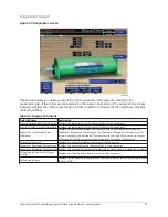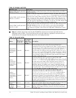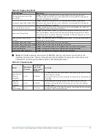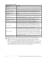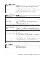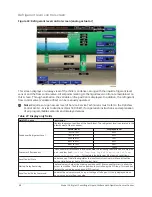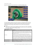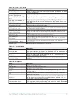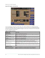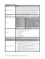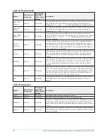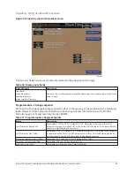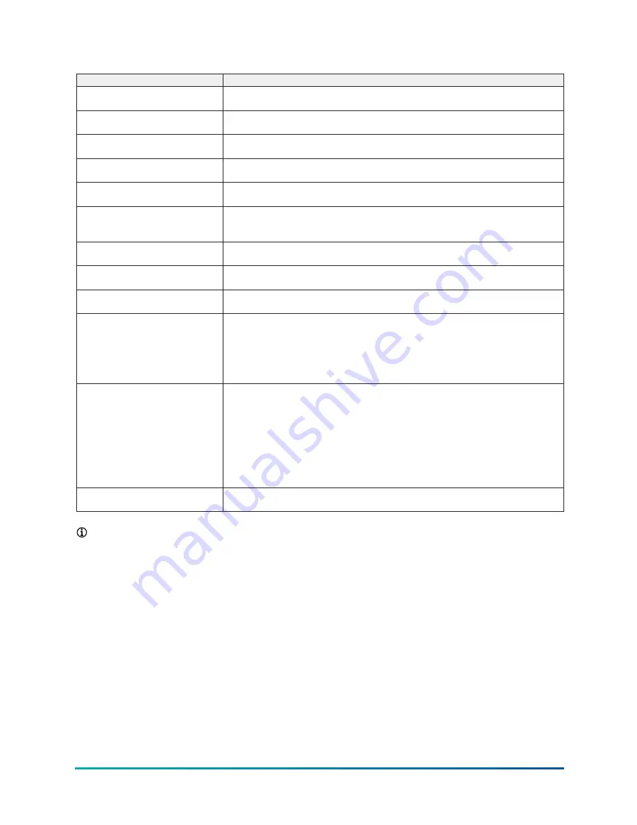
Table 18: Display only fields
Field/LED name
Description
Entering Heating Condenser Liquid
Temperature
Displays the temperature of the liquid as it enters the heating condenser tube bundle.
Leaving Heating Condenser Liquid
Temperature
Displays the temperature of the liquid as it leaves the heating condenser tube bundle.
Active Hot Water Setpoint
Displays the Hot Water Setpoint to which the Leaving Heating Condenser Liquid
Temperature is being controlled. Only appears when Hot Water Control is enabled.
Entering Condenser Liquid
Temperature
Displays the temperature of the liquid as it enters the standard condenser tube
bundle.
Leaving Condenser Liquid
Temperature
Displays the temperature of the liquid as it leaves the standard condenser tube
bundle.
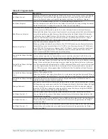
Head Pressure
Displays the pressure difference between the condenser and evaporator (condenser
minus evaporator). This is also called the Head Pressure. Only appears when Head
Pressure Control is enabled.
Head Pressure Setpoint
Displays the active Head Pressure Setpoint to which the head pressure is being
controlled. Only appears when Head Pressure Control is enabled.
Heating Condenser Liquid Flow
Switch (LED)
Displays the status of the flow switch in the heating condenser tube bundle.
Illuminates when liquid flow is present. Otherwise, it is extinguished.
Condenser Liquid Flow Switch (LED) Displays the status of the flow switch in the standard condenser tube bundle.
Illuminates when liquid flow is present. Otherwise, it is extinguished.
PID Control Mode
Only appears when Hot Water Control is enabled. Displays the function the Control
Valve is controlling. If the chiller is equipped with both Heat Recovery and Head
Pressure Control and both are enabled, there is not a control valve for each feature.
Rather, there is one common valve that is either performing Hot Water Control for
Heat Recovery or it is performing Head Pressure Control. It will not be performing
control for both features at the same time. See the following note.
Control Valve Output
Displays the position command being sent to the control valve. If Hot Water Control
is enabled and there is flow in the Heating Condenser, the valve is performing Heat
Recovery Control. Otherwise, if Head Pressure Control is enabled, it is performing
Head Pressure Control. Displayed over the range of 0.0% to 100%. The actual value
of the output signal for a given error depends on whether the PID Output Setpoint is
set to direct or reverse. If set to direct, the 0.0% output will be at minimum; the 100%
output will be at maximum. If set to reverse, the 0.0% output will be at maximum; the
100% output will be at minimum. Only appears when Hot Water Control is enabled or
Head Pressure Control is enabled.
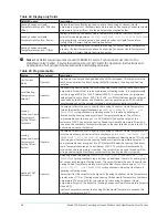
Control Valve Control Mode
Displays whether the Control Valve is in automatic or manual control. Only appears
when Hot Water Control is enabled or Head Pressure Control is enabled.
Note:
Normally, the control valve performs hot water control unless certain operating
conditions cause it to switch over to head pressure control. When performing hot water
control,
Hot Water
is displayed. When performing head pressure control,
Head Pressure
is
displayed. There are also conditions under which it is not controlling either one, in which case
Inactive
is displayed. The feature that controls the valve at any given time and when it is
inactive is determined by operating conditions as shown in the flowchart in the Heat Recovery
Section in
OptiView Control Center – Service Instructions (Form 160.76-M1)
.
Model YK Style H Centrifugal Liquid Chillers with OptiView Control Center
40
Содержание YK Style H
Страница 2: ...2 Model YK Style H Centrifugal Liquid Chillers with OptiView Control Center...
Страница 6: ...6 Model YK Style H Centrifugal Liquid Chillers with OptiView Control Center...
Страница 202: ...Figure 87 Sample printout status cont Model YK Style H Centrifugal Liquid Chillers with OptiView Control Center 202...
Страница 203: ...Figure 88 Sample printout setpoints 203 Model YK Style H Centrifugal Liquid Chillers with OptiView Control Center...
Страница 204: ...Figure 89 Sample printout setpoints cont Model YK Style H Centrifugal Liquid Chillers with OptiView Control Center 204...
Страница 205: ...Figure 90 Sample printout schedule 205 Model YK Style H Centrifugal Liquid Chillers with OptiView Control Center...
Страница 206: ...Figure 91 Sample printout sales order Model YK Style H Centrifugal Liquid Chillers with OptiView Control Center 206...
Страница 207: ...Figure 92 Sample printout sales order cont 207 Model YK Style H Centrifugal Liquid Chillers with OptiView Control Center...
Страница 208: ...Figure 93 Sample printout history Model YK Style H Centrifugal Liquid Chillers with OptiView Control Center 208...
Страница 209: ...Figure 94 Sample printout history cont 209 Model YK Style H Centrifugal Liquid Chillers with OptiView Control Center...

