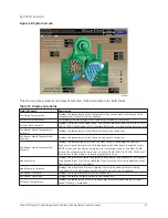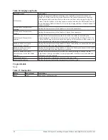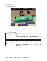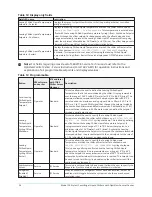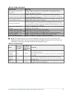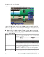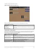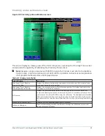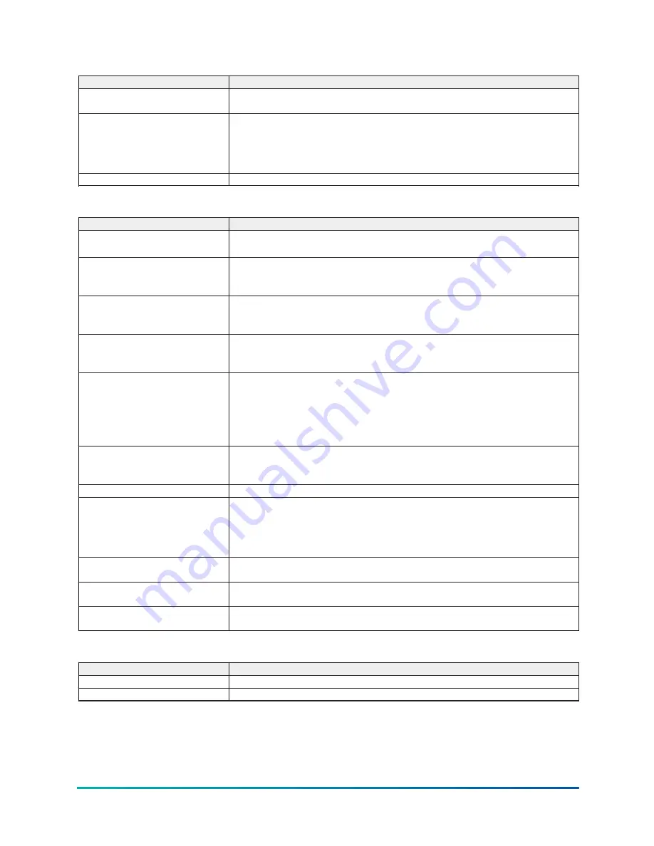
Table 21: Display only fields
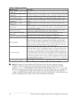
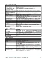
Field/LED name
Description
Head Pressure Setpoint
Displays the active Head Pressure Setpoint to which the head pressure is being
controlled.
Control Valve Command
Displays the position command being sent to the Control Valve. Displayed over the
range of 0.0% to 100%. The actual value of the output signal for a given error depends
on whether the PID Output Setpoint is set to direct or reverse. If set to direct, the 0.0%
output will be at minimum; the 100% output will be at maximum. If set to reverse, the
0.0% output will be at maximum; the 100% output will be at minimum.
Control Valve Control Mode
Displays whether the Control Valve is in automatic or manual control.
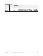
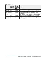
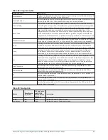
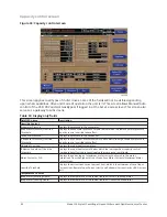
Table 22: Programmable
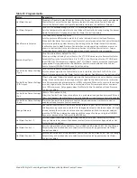
Button
Description
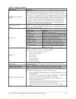
Head Pressure Setpoint
(15.0 to 60 PSID; default 23.0 PSID)
Sets the pressure differential to which the Control Valve will control the Head Pressure.
Minimum Position
(0.0% to 100%; default 0.0%)
Sets the head pressure control valve minimum position to maintain adequate
condenser water flow to the chiller when running.
Shutdown Position
(0.0% to 100%; default 0.0%)
Sets the head pressure control valve to the position desired when the chiller is not
running.
Control Valve Output Settings – Type
(0 V to10 V, or 4 mA to 20 mA; default 0 V to 10 V)
Sets the output signal to the Control Valve to be in the form of either 0 to 10 VDC or 4
to 20mA.
Control Valve Output Settings –
Direction
(Direct or Reverse)
Allows the output signal to the Control Valve to be set to direct or reverse acting.
When set to direct, the voltage or current signal to the Control Valve is at minimum
for a 0% command and at maximum for a 100% command. When set to reverse, the
voltage or current signal to the Control Valve is at maximum for a 0% command and at
minimum for a 100% command.
Control Valve Output Settings – Set
(0.0% to 100%; default 0.0%)
Allows the Control Valve to be manually set to a pre-determined position between
0.0% and 100%.
Control Valve Output Settings – Auto Places the Control Valve in automatic control.
Change Setpoints
Use to enter the Head Pressure Control PID variables below. Pressing this key places a
green box around the first changeable setpoint. Use the up/down, left/right arrows to
place the selection box around the desired setpoint. With the setpoint selected, press
the Enter key. A dialog box appears with the range of settings. Using the numeric keys,
enter desired value. Then, press the Enter key.
Head Pressure Control – P
Sets the Proportional Gain of the Head Pressure Control (0.00 to 5.00; default 2.00).
Use the Change Setpoints key as described above to select/enter this setpoint.
Head Pressure Control – I
Sets the Integral Gain of the Head Pressure Control (0.00 to 5.00; default 2.00). Use the
Change Setpoints key as described above to select/enter this setpoint.
Head Pressure Control – D
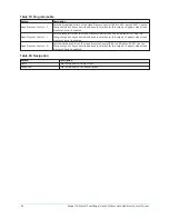
Sets the Derivative Gain of the Head Pressure Control (0.00 to 5.00; default 0.00). Use
the Change Setpoints key as described above to select/enter this setpoint.
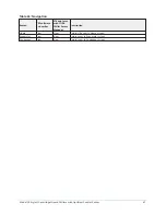
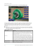
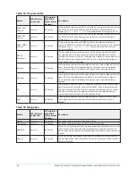
Table 23: Navigation
Button
Description
Home
Returns the user to Home screen.
Condenser
Returns the user to Condenser screen.
Model YK Style H Centrifugal Liquid Chillers with OptiView Control Center
44
Содержание YK Style H
Страница 2: ...2 Model YK Style H Centrifugal Liquid Chillers with OptiView Control Center...
Страница 6: ...6 Model YK Style H Centrifugal Liquid Chillers with OptiView Control Center...
Страница 202: ...Figure 87 Sample printout status cont Model YK Style H Centrifugal Liquid Chillers with OptiView Control Center 202...
Страница 203: ...Figure 88 Sample printout setpoints 203 Model YK Style H Centrifugal Liquid Chillers with OptiView Control Center...
Страница 204: ...Figure 89 Sample printout setpoints cont Model YK Style H Centrifugal Liquid Chillers with OptiView Control Center 204...
Страница 205: ...Figure 90 Sample printout schedule 205 Model YK Style H Centrifugal Liquid Chillers with OptiView Control Center...
Страница 206: ...Figure 91 Sample printout sales order Model YK Style H Centrifugal Liquid Chillers with OptiView Control Center 206...
Страница 207: ...Figure 92 Sample printout sales order cont 207 Model YK Style H Centrifugal Liquid Chillers with OptiView Control Center...
Страница 208: ...Figure 93 Sample printout history Model YK Style H Centrifugal Liquid Chillers with OptiView Control Center 208...
Страница 209: ...Figure 94 Sample printout history cont 209 Model YK Style H Centrifugal Liquid Chillers with OptiView Control Center...


