<6. PROCEDURES FOR CONVERTER OPERATION>
6-16
IM 12E04A02-02E
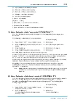
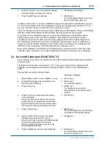
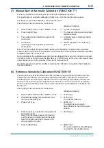
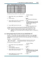
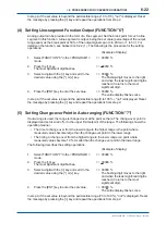
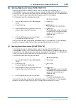
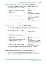
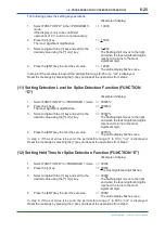
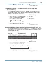
6. Select a digit with the [>] key and set the
=> 0100.0 mg/l
turbidity value of the standard solution using the
[^] or [v] key. Every time the [>] key is pressed,
the
fl
ashing digit moves to the right and when
the least signi
fi
cant digit is reached, it moves to
the second digit from the left.
7. Press the [ENT] key to terminate calibration.
=> 0100.0 mg/l
The entire display
fl
ashes once and
the CAL lamp goes out.
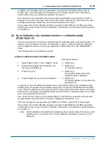
If the turbidity value set in operation 7 exceeds the permissible setting range (0 to 2200 mg/l),
"not" is displayed. In this case, the "FAIL" lamp is not lit and a FAIL contact is not output. Reset
the error message by pressing the [ENT] key and continue operation from step 2.
Also in reference sensitivity calibration, the permissible sensitivity range is not speci
fi
cally
determined in calibration. If calibration of this function is performed, the slope display in the
<MEAS.> mode becomes 100.0 %. In any stage of reference sensitivity calibration operation,
pressing the [MODE] key or [FUNC] key allows switching to another mode or function. The
calibration computation is not performed unless operation 7 is carried out.
Note: At this calibration, the turbidity not multiplied by the correction factor from the zero-shift
calibration (zero correction) in (3) or span calibration (sensitivity correction) in (5) is
displayed.
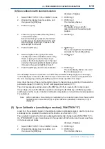
(9) Converter Check Operation (FUNCTION "9")
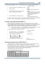
This operation checks the operation of the converter by switching the converter input signal from
a measured signal to a simulated signal.
The following is the procedure for this function.
(Example of display)
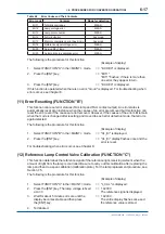
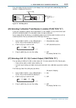
1. Select FUNCTION "9" in the <MAINT.> mode.
=> "C.CHEC" is displayed.
2. Press the [ENT] key.
=> 0050.0 mg/l
The converter is normal if the turbidity reading and analog output satisfy the following conditions:
Turbidity reading: 50.0 ±0.5 mg/l
Analog output:
12.00 ± 0.16 mA (or 4 to 20 mA output)
3.00 ±0.05 V
(for 1 to 5 V output)
If the analog output in the maintenance mode is set to "hold", the analog output is held at 12 mA
(or 3 V) in this operation. When the mode or function is switched to <MEAS.> mode using the
[MODE] key, the converter input returns to a measured signal from the simulated input. In this
case, a little time is needed until the reading becomes stable (1 minute or more).
Note: The time required for the reading to stabilize in returning to a measured signal from the
simulated input depends on the averaging coef
fi
cient preset in FUNCTION "4" in the
<PROGRAM1> mode.
If the data (30) set on shipment from the factory are changed, the extra time is needed.
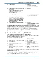
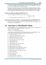
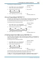
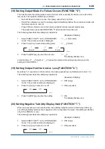
(10) Error Code Display (FUNCTION "A")
If the FAIL lamp is lit, an error code is not displayed at the time of an error occurrence.
This function is used to con
fi
rm an error code. Table 6.8 shows error codes displayed with this
function and their contents.
3rd Edition : May. 31, 2010-00
Содержание Vigilant Plant EXA TB Series
Страница 49: ...Blank Page ...
Страница 59: ...Blank Page ...
Страница 119: ...Blank Page ...
Страница 125: ...Blank Page ...
Страница 127: ...Blank Page ...
Страница 133: ...Blank Page ...

