


<8. TROUBLESHOOTING>
8-4
IM 12E04A02-02E
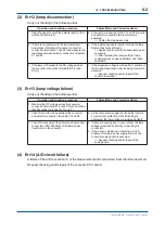
(9) Err25 (lamp service life ended)
Operation and checking procedure
Failure Mode and Corrective Action
1. Measure the DC voltage across the converter
connection terminals [P1(+) and P2(-)]. Con
fi
rm
that it is about 4.8 V*.
a. The lamp brightness decreases and the lamp
voltage shows the upper control limit (about 4.8
V*).
=> Replace the lamp with the spare lamp.
* If the program version number is 1.08, the upper limit is set to 4.1 V. (The version number can be con
fi
rmed in FUNCTION "E" in
<MAINT.> mode. Refer to Subsection 6.5 (13).)
Note: If the lamp life alarm occurs, turbidity measurement does not immediately become impossible.
If the lamp life alarm occurs, since the lamp voltage is
fi
xed at about 4.1 V, turbidity measurement can be contained in this state.
However, since the lamp voltage is not controlled, measurement error gradually increases. Thus, replace the lamp as soon as
possible.
NOTE
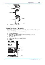
After replacing the lamp, perform running-in for an hour or more and then perform lamp control
reference value calibration and turbidity span calibration.
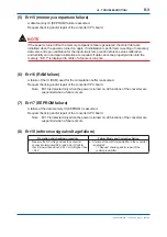
(10) Err26 (automatic calibration failure)
In automatic zero calibration, the zero-calibration permissible range is exceeded. The cause
is assumed to be a failure in the operation of the motor-operated drain valve (SV1) or motor-
operated measuring water valve (SV3), clogging of the piping between the detector and the head
tank, etc.
Operation and checking procedure
Failure Mode and Corrective Action
1. Select the <MAINT.> mode and check the open/
shut operations by turning valves SV1 and SV3 on
and off.
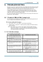
2. If the valve(s) does(do) not operate properly, turn
off the power to the converter one time and remove
the motor-operated valve wiring from the converter
connection terminal board (Table 8.1).
3. Turn on the power again and check whether the
valve driving voltage (power voltage) appears
across the terminals by doing an on/off operation
using the SV key (Table 8.1).
a. If the normal driving voltage is not output, a failure
of the valve driving circuit on the converter analog
board is assumed.
=> Request checking and/or repair of the analog
board.
b. If the normal driving voltage is output, a failure of
the motoroperated valve(s) is assumed.
=> Replace the motor-operated valve(s) with good
one(s).
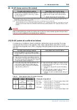
Table 8.1 Motor-operated Valve Connection Terminals
Terminal
Valve
Function
V1
V2
V3
SV1
(Pinch valve)
Open, Closed
—
COM
V4
V5
V6
SV3
(Motor valve)
Open
Closed
COM
3rd Edition : May. 31, 2010-00
<Example of operation>
SV1 open
→
Across V1 and V3: Power supply voltage output
SV1 closed
Across V1 and V3: 0 V output
SV3 open
→
Across V4 and V6: Power supply voltage output
Across V5 and V6: 0 V output
SV3 closed
→
Across V4 and V6: 0 V output
Across V5 and V6: Power supply voltage output
Содержание Vigilant Plant EXA TB Series
Страница 49: ...Blank Page ...
Страница 59: ...Blank Page ...
Страница 119: ...Blank Page ...
Страница 125: ...Blank Page ...
Страница 127: ...Blank Page ...
Страница 133: ...Blank Page ...


