<5. FUNCTIONS>
5-3
IM 12E04A02-02E
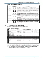
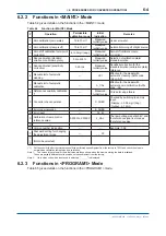
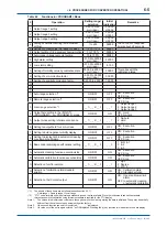
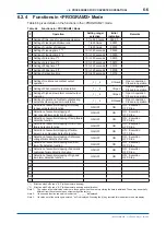
•
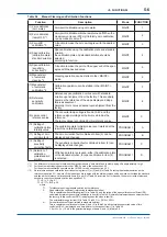
In the "FAIL lamp" column,
○
means the lamp lights and × the lamp goes out.
• The items for detected failures for which both the mode and function are described can be selected for execution/stop of
detection (see Section 6.7).
• Errors detected other than in calibration are automatically reset at the time when the cause of failure is removed.
• If the "FAIL" lamp is lit, error numbers can be con
fi
rmed with FUNCTION "A" in the <MAINT.> mode, while the error can be reset
with FUNCTION "B" in the <MAINT.> mode.
• If the "FAIL" lamp is lit, analog output mode selection (non-hold, hold, or preset) is possible with FUNCTION "5" in the
<PROGRAM1> mode.
• If the"FAIL" lamp is lit, FAIL contact output is also obtained.
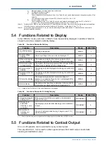
• If an Err11 to 15, Err18, Err25, or Err26 failure is detected, error numbers are output by virtue of digital output (see Section 2.1,
digital communication speci
fi
cations).
• If Err16 or Err17 is detected, other operations cannot be accepted with the error number displayed.
(*1)
The TB400G controls the lamp voltage so that a constant light quantity is obtained. If the amount of lamp light diminishes, the
lamp voltage increases.
Thus, the lamp voltage may be an index for the life of the lamp.
(*2)
Err26 is detected only if the speci
fi
cations are for automatic zero-calibration (Suf
fi
x code: -A3).
(*3)
15 high and low alarm setpoints can be set using FUNCTION "8" and "9" in the <PROGRAM1> mode.
(*4)
If the program version number is 1.08, the upper limit is set to 4.1 V. (The version number can be con
fi
rmed in FUNCTION "E" in
<MAINT.> mode. Refer to Subsection 6.5 (13).)
5.2 Functions Related to Analog Output
5.2.1
Output Range Selection
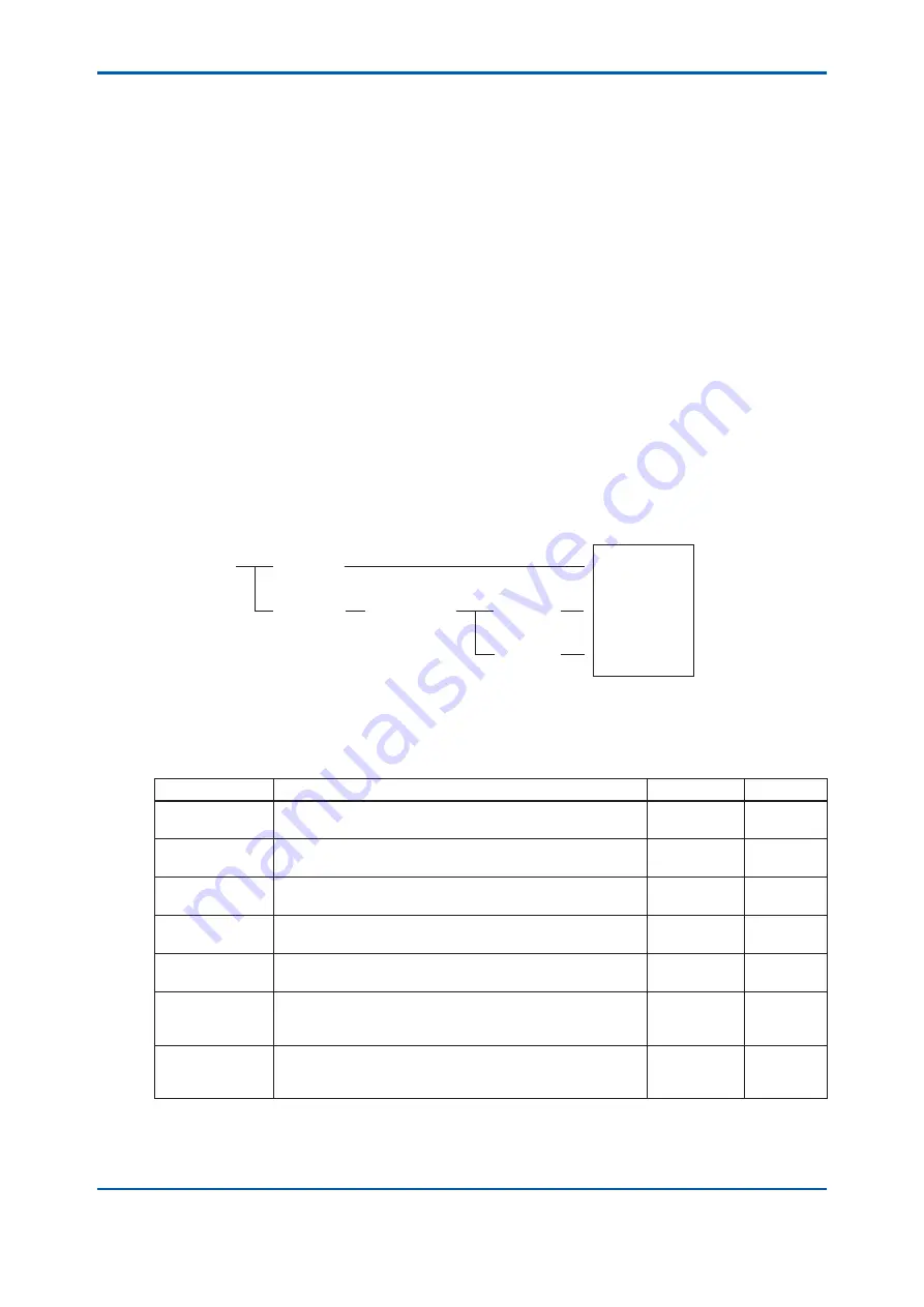
The output range can be set up in three ways: auto range, remote range, and local range.
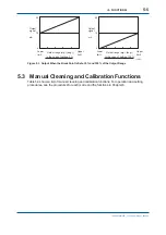
The relationship between these is as shown in Figure 5.1. Table 5.2 shows the setting modes and
function numbers related to the output range selection.
F0501.ai
Auto-range
Execution
Stop
Remote range
Execution
Stop
Operation
Auto-range
Remote range
Local range
(Note)
The turbidimeter is shipped with the output range set to 1 for the local range.
Figure 5.1 Output Range Selection
Table 5.2 Function Related to Output Range Selection
Detected item
Details
Mode
FUNCTION
1) Output range
1 setting
The upper and lower limits for analog output 1 are set.
PROGRAM 1
1.
2) Output range
2 setting
The upper and lower limits for analog output 2 are set.
PROGRAM 1
2
3) Output range
3 setting
The upper and lower limits for analog output 3 are set.
PROGRAM 1
3
4) Auto-range
selection
The function that automatically switches the output ranges
(1, 2, and 3) depending on the turbidity value.
PROGRAM 1
1.
5) Remote range
selection
The function that switches the output ranges (1, 2, and 3) by
contact inputs (R1, R2, and R3) (when function 4) is "oFF").
PROGRAM 1
2.
6) Local range
selection
The function that switches the output ranges (1, 2, and 3)
using converter key operations (when function 4) and 5) are
"oFF").
PROGRAM 1
3.
7) Auto-range
switching point
setting
The auto-range switching point is arbitrarity set when auto-
range is used.
PROGRAM 1
7
• Corresponding to switching of the output range, the range contact outputs (A1, A2, A3, A4) are switched and the RNG1, RNG2, or
RNG3 lamp is lit.
(1) Output range 1: Range contact outputs A1 and A2 are closed; RNG1 lamp is lit.
(2) Output range 2: Range contact outputs A1 and A3 are closed; RNG2 lamp is lit.
(3) Output range 3: Range contact outputs A1 and A4 are closed; RNG3 lamp is lit.
3rd Edition : May. 31, 2010-00
Содержание Vigilant Plant EXA TB Series
Страница 49: ...Blank Page ...
Страница 59: ...Blank Page ...
Страница 119: ...Blank Page ...
Страница 125: ...Blank Page ...
Страница 127: ...Blank Page ...
Страница 133: ...Blank Page ...


