YOKOGAWA CW240 Скачать руководство пользователя страница 329

15-2

IM CW240E

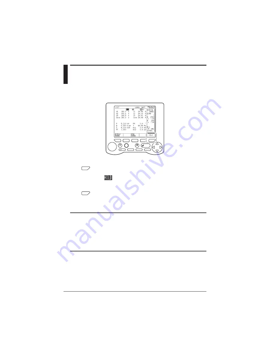
15.1  Holding the Display Value

The display screen (display values) are held when the F5 (HOLD) key is
pressed during measurement.

LIGHT

TOP

MENU

SAVE

A

RANGE

START

&STOP

ESC

ENTER

F

1

F

2

F

3

F

4

F

5

DISP COPY

RANGE

<Hold>

F

5

Press the HOLD (F5) key.

The display screen is held.

  is displayed at the top middle of the screen during the hold.

<Clear Hold>

F

5

Press the HOLD (F5) key in hold status.

Hold will be cleared.

TIP

• Measurement (internal operation) is performed during hold.

• HOLD/CLEAR is displayed when integration data (integration values) has been saved.

The integration values are cleared if the F5 key is pressed continuously for 3 sec-
onds or longer.

• Setting confirmation cannot be performed during hold.

• When saving (printing) the screen with the DISP COPY key, it is recommended that

the save (print) be done after holding the display value with the hold function.

Chapter 15  Other Functions

Содержание CW240

Страница 1: ...User s Manual CW240 Clamp on Power Meter IM CW240E 1st Edition June 2004 KP IM CW240E ...

Страница 2: ...tor Block 2 2 2 2 Operation Keys 2 3 2 3 Side Faces 2 4 2 4 Screen Configuration 2 5 2 5 Overrange Error Indication during Measurement 2 6 2 6 Description of Mark Indication 2 11 Chapter 3 Preparation for Safe Measurements 3 1 3 1 Precautions for Use 3 2 3 2 Connecting a Power Supply 3 4 3 3 Connecting Voltage Probes 3 14 3 4 Connecting Clamp on Probes 3 15 3 5 Connection Diagrams of Voltage Probe...

Страница 3: ... 7 Checking Wiring 4 24 Chapter 5 Setting Ranges Using the Direct Keys 5 1 5 1 Setting the Voltage Range 5 2 5 2 Setting the Current Range 5 4 5 3 Ranges and Number of Digits 5 6 Chapter 6 Configuring Settings 6 1 6 1 Settings 6 2 6 2 General Settings 1 2 6 6 6 3 General Settings 2 2 6 21 6 4 Save Data Settings 1 2 6 46 6 5 Save Data Settings 2 2 6 62 6 6 Communication Settings 6 67 6 7 Voltage Qu...

Страница 4: ...nt Data 7 46 Chapter 8 Saving Measured Data 8 1 8 1 Data Save 8 2 8 2 Saving Measured Data 8 6 8 3 Memory Reference 8 11 8 4 Backup Memory 8 13 8 5 Copying Screen Data Hard copy 8 15 Chapter 9 Processing File s 9 1 9 1 File Processing 9 2 9 2 Changing a File Name 9 4 9 3 Deleting a File 9 6 9 4 Formatting 9 9 9 5 Data Copy 9 10 9 6 Setting Files Load Save Delete Name Change 9 14 9 7 Backup Memory ...

Страница 5: ...tional 13 1 13 1 Analog Output DA Output 13 2 13 2 Analog Input 13 6 13 3 Connecting Analog Input Output Terminals 13 8 Chapter 14 Power Failure Processing Function 14 1 Chapter 15 Other Functions 15 1 15 1 Holding the Display Value 15 2 15 2 Turning the LCD Backlight ON and OFF 15 3 15 3 Locking the Keys 15 4 15 4 Resetting the System 15 5 Chapter 16 Maintenance Troubleshooting 16 1 16 1 Things t...

Страница 6: ...nt Item Descriptions App 2 1 Appendix 3 Polarity Active Power Reactive Power Power Factor Phase Angle App 3 1 Appendix 4 Polarity Harmonic Measurement App 4 1 Appendix 5 Reactive Power Method App 5 1 Appendix 6 Sampling Method App 6 1 Appendix 7 Terminolo App 7 1 Index ...

Страница 7: ...l come in handy when you are unsure of how to operate the product Notices The contents of this manual are subject to change without prior notice In addition figures and illustrations representing display views in this manual may differ from actual views Every effort has been made to ensure accuracy in the preparation of this manual However should any doubts arise or errors come to your attention p...

Страница 8: ...input Clamp on current probe for 96030 2 pcs set Clamp on current probe for 96030 4 pcs set Clamp on current probe for 96031 2 pcs set Clamp on current probe for 96031 4 pcs set Clamp on current probe for 96032 2 pcs set Clamp on current probe for 96032 4 pcs set Clamp on current probe for 96033 2 pcs set Clamp on current probe for 96033 4 pcs set Clamp on current probe for 96036 2 pcs set Clamp o...

Страница 9: ...e from any damage Product Name Part No Q ty Remarks 1 AC adapter for 788011 1set Yokogawa s AC adapter power supply 2 AA size alkaline 6 batteries 3 Voltage probes 91007 4 Color black red yellow blue 4 User s Manual IM CW240 1 5 Quick Setup IM CW240P 1 Manual 6 CD ROM 1 1 2 3 4 5 6 Checking the Contents of the Package ...

Страница 10: ...diameter type Selectable from 3000 A 2000 A and 1000 A for 3000 A 96035 1 Flexible type Selectable from 3000 A and 300 A for 2 A 96036 1 Voltage probe 91007 1 set 4 Carrying case 93020 1 AC adapter 788011 1 set Yokogawa s AC adapter NiMH battery pack 94004 AC adapter for 96035 A1020UP 1 For clamp on Probes Printer 97010 1 AC adapter for printer Europe 94006 1 AC adapter for printer USA 94007 1 The...

Страница 11: ... its clamp on probes and voltage probes connected to the unit The case can also house such accessories as the memory card AC adapter and User s Manual As such it comes in handy for transporting a complete kit of tools necessary for making measurements Example of Housing User s Manual NiMH battery pack AC adapter Clamp on probes CW240 main unit Voltage probes ...

Страница 12: ...ator must refer to an explanation in the User s Manual in order to avoid risk of injury or death of personnel or damage to the instrument Hazardous Voltage The operator must never attempt to touch equipment or parts marked with this symbol Direct Current This symbol indicates DC voltage current Alternating Current This symbol indicates AC voltage current ON This symbol indicates On power OFF This ...

Страница 13: ...ble modify the instrument itself Some parts of the inside of the instrument contain high voltage and therefore access to the internal assembly is extremely hazardous For inspection and or adjustment of the internal assembly contact the vendor from which you purchased the instrument Use of the Instrument in a Gaseous Atmosphere Do not operate the instrument in a location where any flammable or expl...

Страница 14: ...allow the power cord to come into accidental contact with any heat source When unplugging the power cord from the outlet hold its plug rather than holding and pulling the cord itself If the power cord is damaged contact the vendor from which you purchased the instrument Measures in Case of Anomalies If the instrument begins to emit smoke becomes too hot or gives off an unusual smell immediately tu...

Страница 15: ...truction afin d éviter un accident au person nel ou de protéger l appareil Haute tension Ne pas toucher Courant continu Ce symbole indique une tension intensité C C Courant alternatif Ce symbole indique une tension intensité C A MARCHE Ce symbole indique la mise sous tension ARRET Ce symbole indique la mise hors tension Double isolation Ce symbole indique une double isolation AVERTISSEMENT Indique...

Страница 16: ...trument sous tension toujours s assure que sa ten sion correspond à celle de la source d alimentation En cas d utilisation de piles alcalines ou d un accumulateur NiMH lire attentivement les mises en garde relatives à la manipulation des piles accumulateurs plus loin das ce manuel Utilisation des sondes d intensité à pince Lors de l utilisation des sondes d intensité à pince maintenir la tension d...

Страница 17: ...vendeur auprès duquel a été acheté l instrument Mesures à prendre en cas d anomalies Si l instrument est brûlant dégage de la fumée ou une odeur inhabituelle le mettre immédiatement hors tension et débrancher le cordon d alimentation de la prise secteur Mettre également hors tension le circuit sur lequel est effectuée la mesure et qui est raccordé aux bornes d entrée de l instrument Ne surtout pas...

Страница 18: ...Chapter 1 Product Overview Chapter 1 Product Overview 1 1 Product Overview 1 2 1 2 System Configuration Diagram 1 4 ...

Страница 19: ...ent rms content phase angle power value power content and power phase angle Indication is available as a list bar graph and vector diagram Voltage fluctuation Voltage dip swell momentary interruption Voltage quality Data is saved by a threshold value based trigger Waveform Voltage and current waveform full voltage waveform full current waveform Features Supporting a Variety of Wiring Methods Wirin...

Страница 20: ...equence or reverse connection of clamp on current probes The setup check function allows you to check settings for integration measurements Data management and communication Data can be saved using a personal computer PC card Data can be transferred to a PC and setup can be made from the PC through communications Equipped with 4CH DA outputs and 2CH analog inputs DC V optional Measured values can ...

Страница 21: ...rements using multiple instruments External control input output RS 232 PC Printer AC adapter MV series recorders DA outputs 4 CH Analog inputs 2 CH 53003 thermometer 510 series illuminometer PC card Alkaline batteries NiMH battery pack Chapter 13 Section 6 9 Chapter 3 Sections 3 3 and 3 5 Sections 3 4 and 3 5 Chapter 3 3 2 1 Chapter 10 Chapter 12 Chapter 3 3 2 2 3 2 3 Chapter 11 Chapter 13 Sectio...

Страница 22: ...hapter 2 Part Names and How to Use Parts 2 1 Front Panel and Connector Block 2 2 2 2 Operation Keys 2 3 2 3 Side Faces 2 4 2 4 Screen Configuration 2 5 2 5 Overrange Error Indication during Measurement 2 6 2 6 Description of Mark Indication 2 11 ...

Страница 23: ...le Used for DC voltage inputs Allows you start or stop integration measurements using an external signal Also a signal indicating that an integration measurement is being made is output through these terminals Display unit Used for DC voltage outputs Voltage input terminals Current input terminals RS 232 connector Analog input terminals optional External control I O terminals DA output terminals o...

Страница 24: ...isplayed in the bottom of the screen START STOP key Starts stops integration measurements LIGHT key Turns the backlight ON OFF When held down for more than 3 seconds it locks or unlocks the operation keys TOP MENU key Switches the display screen to the Top Menu ESC key ENTER key Cancels setup conditions or other data Confirms setup conditions or other data Cursor key Moves the cursor to the item y...

Страница 25: ... battery holder Lights up while a NiMH battery pack optional is charged Connect the AC adapter accessorie to this jack LED AC adapter jack Battery holder Battery holder lock switch Power OFF Power ON Power switch This part holds the alkaline battery holder accessorie or NiMH battery holder optional ...

Страница 26: ...ETE FILE FORMAT DATA COPY SETTING FILE BACKUP MEMORY COPY BACKUP MEMORY DELETE PROGRAM UPDATE normally not used MEASURE screen SETUP screen FILE screen LIST instantaneous values POWER INTEGRATE DEMAND ZOOM HARMONIC LIST GRAPH VECTOR WAVEFORM U I WAVEFORM U WAVEFORM I WAVEFORM VOLT QUALITY WIRING DIAGRAM WIRING CHECK GENERAL 1 2 2 2 SAVE 1 2 2 2 COMMUNICATION VOLT QUALITY HARDWARE ANALOG I O option...

Страница 27: ...e mark appears if an input signal to one of terminals U1 to U3 satisfied the noted conditions Current overrange mark appears if an input signal to one of terminals CH1 to CH4 satisfies the noted conditions Indication of OR or symbol The CW240 indicates OR or symbol instead of a usual four digit value if the measured value meets the noted conditions WARNING The CW240 shows an overrange mark in the ...

Страница 28: ...ts 9999 OR appears Power factor Phase angle If the peak value of a voltage input signal exceeds 300 180 for a 1000 V range of the measurement range if the rms value of measured voltage exceeds 130 of the rated range if the peak value of a current input signal exceeds 400 of the measurement range or if the rms value of measured current exceeds 130 of the rated range appears Frequency If frequency e...

Страница 29: ...peak value of an input signal exceeds 400 of the measurement range or if the rms value of measured current exceeds 130 of the rated range appears Power value If a power input exceeds 130 of the rated range OR appears Also if the measured value exceeds the maximum displayable digits 9999 OR appears Power content Power phase angle If the peak value of a voltage input signal exceeds 300 180 for a 100...

Страница 30: ...ange the reading becomes 0 Var If an input level is 0 17 or less of the rated range the reading becomes 0 VA If power input is 0 17 or less of the rated range integration stops If reactive power input is 0 17 or less of the rated range integration stops If the input level of either voltage or current is below 0 4 of the rated range appears If frequency is 40 Hz or less or if the input level of a f...

Страница 31: ...n Because of a computation error if the power factor Exceeds 1 0 the reading becomes 1 0 Is less than 1 0 the reading becomes 1 0 Is S P the reading becomes 1 0 Because of a computation error if the power factor Exceeds 1 0 the reading becomes 1 0 Is less than 1 0 the reading becomes 1 0 If the power factor exceeds 1 0 or is less than 1 0 due to a computation error the reading becomes 0 If the tot...

Страница 32: ...shes during an access to the PC card Appears when data has been saved in the backup memory Appears when the CW240 is configured so that data is saved in the internal memory Also this mark flashes during an access to the internal memory Appears if the CW240 is in a key lock state Appears when the CW240 is configured so that the RS 232 connection destination is a PC Also this mark flashes during com...

Страница 33: ... 1 Precautions for Use 3 2 3 2 Connecting a Power Supply 3 4 3 3 Connecting Voltage Probes 3 14 3 4 Connecting Clamp on Probes 3 15 3 5 Connection Diagrams of Voltage Probes and Clamp on Probes 3 17 3 6 Turning ON the Power Switch 3 22 3 7 Performing Measurements with Greater Precision 3 24 ...

Страница 34: ...rotection of the case or operation panel Do not pour volatile chemicals on the case or operation panel or leave any rubber or PVC product in contact with the case or operation panel for a prolonged period otherwise the case and or operation panel may be discolored or deformed Cleaning When cleaning the case and or operation panel disconnect the power cord from the outlet and gently wipe the extern...

Страница 35: ...on assembled to ensure high performance When using a clamp do not apply any intense mechanical shock vibration or force to the clamping CT If dust or any other foreign matter gets in the clamping CT do not shut the clamping cores tight First remove dust and then make sure the clamping cores on both sides close smoothly 3 1 Precautions for Use ...

Страница 36: ...notes when handling the AC adapter WARNING Use only the Yokogawa supplied dedicated power cord Check that the power source voltage matches the supply voltage rating of the AC adapter and then connect the power cord to the outlet Check that the power switch of the CW240 is turned OFF and then connect the power cord If the CW240 is not used for a prolonged period disconnect the AC adapter power cord...

Страница 37: ... Connect the AC adapter plug to the CW240 s AC adapter jack 3 Connect the plug of the power cord supplied with the AC adapter to the power connector of the AC adapter 4 Connect the other end of the power cord to the power outlet that meets the power rating requirements AC adapter s Power Rating Supply voltage ratin 100 to 240 V AC Allowable supply voltage range 90 to 264 V AC Power supply frequenc...

Страница 38: ...e the batteries heat them up or dispose of them in a fire Do not short the batteries Do not attempt to recharge the batteries Do not solder the batteries When replacing the batteries replace all six units at the same time with new ones of the same manufacturer Do not use manganese batteries as replacements If the CW240 will not be used for a prolonged period remove the batteries Backup Hours by Al...

Страница 39: ...is operated using alkaline batteries the following mark appears A decrease in the battery voltage remaining capacity is indicated in the following four steps NOTE If you continue to operate the CW240 with this mark displayed the CW240 will be turned OFF automatically Replace the alkaline batteries with new ones before this mark appears ...

Страница 40: ...alkaline batteries 4 Place the battery holder into the holder inlet of the CW240 Then slide the battery holder into the slot so that the battery holder connector connects properly with the battery connector 5 Lower the lock switch on the side of the CW240 to fix the holder The indication changes to 䉭FREE CAUTION Place alkaline batteries into the holder with the positive and negative polarities of ...

Страница 41: ...lean water Then see a doctor quickly for treatment When replacing the NiMH battery pack always turn the CW240 power switch OFF and disconnect the AC adapter power cord from the outlet to avoid possible danger such as a short in the electric circuit or electrical shock Do not use any battery pack other than Yokogawa s NiMH battery pack model 940 04 Do not leave the NiMH battery pack in strong direc...

Страница 42: ...ed for a prolonged period remove it from the CW240 and store it in the following environment Storage period of 1 year or less Temperature of 20 C to 35 C in locations with low humidity Storage period of 3 months or less Temperature of 20 C to 45 C in locations with low humidity Procedure for Installing the NiMH Battery Pack Follow the steps below to install the dedicated NiMH battery pack 1 Check ...

Страница 43: ...ry connector 5 Lower the lock switch on the side of the CW240 to fix the holder The indication changes to 䉭FREE Recharging the NiMH Battery Pack When shipped from the factory the dedicated NiMH battery pack optional is not fully charged for safety reasons Recharge the battery pack to its full level before use When recharging it use the CW240 and AC adapter WARNING When recharging the NiMH battery ...

Страница 44: ...lashing the CW240 is in a waiting to be recharged state The CW240 falls into this state if the ambient temperature is outside the 10 C to 35 C range the battery performance is significantly low due to over discharge or for other rea sons the battery temperature has exceeded 55 C during recharging or the ambient temperature has changed abruptly Indication that Recharging is Required When the CW240 ...

Страница 45: ...Operating Conditions Backup Hours Available LCD backlight OFF Approx 3 hours No access to a PC card NiMH Battery Life The NiMH battery pack can be recharged approximately 300 times though the frequency depends on the operating environment The life of the battery pack is over if the low battery mark appears soon after the battery pack has been fully recharged Replace the battery pack with a new one...

Страница 46: ...per con nection may result in not only damage to the circuit or equipment under test or the CW240 but also an injury to personnel Voltage input terminals N U1 U2 and U3 are not isolated from each other Do not connect any voltage probes not required not used for measurements Also do not touch voltage input terminals not used For measurements do not use any voltage probes other than those supplied w...

Страница 47: ...the circuit or equipment under test or the CW240 but also an injury to personnel Do not connect any clamp on probe not required not used for measurement For measurements do not use any current probes other than those dedicated to the CW240 Do not use a clamp on probe for a non insulated conductor v 1 N v 2 v 3 L L 1CH H L H L H V IN P U T V IN P U T 60 0V60 0V M A X M A X TE R M IN A LS 60 0V M A ...

Страница 48: ...mA 500 mA 1 A 2 A 5 A 10 A 20 A 50 A 20 A 50 A 100 A 200 A 50 A 100 A 200 A 500 A 200 A 500 A 1000 A Current range is selectable using a switch 300 A 750 A 1500 A 3000 A 200 A 500 A 1000 A 2000 A 100 A 200 A 500 A 1000 A Current range is selectable using a switch 300 A 750 A 1500 A 3000 A 30 A 75 A 150 A 300 A Model 96036 for 2 A 96033 for 50 A 96030 for 200 A 96031 for 500 A 96032 for 700 A 1000 ...

Страница 49: ...d Clamp on Probes Single phase two wire Single load 1P2W N 1 Load 1 Black Red N 1 Single phase two wire Two loads 1P2W Black Red Load 1 Load 2 N 1 Single phase two wire Three loads 1P2W Black Red Load 1 Load 2 Load 3 N 1 Single phase two wire Four loads 1P2W Black Red Load 1 Load 4 Load 2 Load 3 ...

Страница 50: ...ellow Load 1 Load 2 N 1 2 1 2 1 2 Single phase three wire Two loads 1P3W Black Red Yellow Load 1 Load 2 N 1 2 1 2 N Single phase three wire three current 1P3W3I Measurement of neutral line current Black Red Yellow 3 5 Connection Diagrams of Voltage Probes and Clamp on Probes ...

Страница 51: ... Two power meter method Black Red Blue R T R T S R T Black Red Blue Load 1 Load 2 Three phase three wire two current Two loads 3P3W2I Two power meter method R S T R S T Three phase three wire three current 3P3W3I Three power meter method Red Yellow Blue 3 5 Connection Diagrams of Voltage Probes and Clamp on Probes ...

Страница 52: ...on Diagrams of Voltage Probes and Clamp on Probes 1 2 3 N 1 3 2 Three phase four wire 3P4W Black Red Yellow Blue 1 2 3 N N 1 3 2 Black Red Yellow Blue Three phase four wire four current 3P4W4I Measurement of neutral line current ...

Страница 53: ...ingle phase Three phase 3 wire Scott connection 3P3W 1P3W Single phase 1P3W connection R S 1 S 2 T R T N R T S Black Red Yellow Blue Single phase Three phase 3 wire Scott connection 3P3W 1P3W Single phase 1P3W connection S T 1 T 2 R R T N R T S Black Red Yellow Blue Single phase Three phase 3 wire Scott connection 3P3W 1P3W Single phase 1P3W connection T R ...

Страница 54: ...del version number the presence of options and self check results CW240 Ver 1 00 FPGA Check OK SDRAM Check OK SRAM Check OK Flash Disk Check OK RTC Check OK EEPROM Check OK Setting Check OK Option Analog In Out 3 When the self check has been completed normally the screen displayed when you previously turned OFF the CW240 appears To switch to the Top Menu screen shown on the left press the TOP MENU...

Страница 55: ...alog In Out Description Model and version number FPGA check SDRAM check SRAM check Check of the flash file system internal memory Check of the real time clock EEPROM Check Setting data check Option specifications The example shows the presence of analog I O CAUTION If an error is detected by the self check 3 to 8 items the information about the error is displayed For countermeasures see Chapter 16...

Страница 56: ...r at least an hour to allow it to adapt to the new ambient temperature and for any condensation to dissolve Then begin operating the CW240 Supply the power of sine waves at 50 Hz 60 Hz When using a clamp on probe pay attention to the following points 1 When performing measurements hold the clamp on probe so that the conductor cable runs through the center of the clamping CT 2 Ensure that the orien...

Страница 57: ... for Wiring to the Measurement Circuit 4 2 4 2 Installing the CW240 4 3 4 3 Setting up Wiring 4 5 4 4 Setting up the Number of Loads 4 6 4 5 Carrying out Wiring 4 7 4 6 Wiring the Measurement Circuit Using External VT CT 4 23 4 7 Checking Wiring 4 24 ...

Страница 58: ...T III 96030 200 A 250 A 300 V CAT II 600 V CAT II 96031 500 A 625 A 300 V CAT II 600 V CAT II 96032 700 A continuous 700 A continuous 600 V 1000 A for 5 min 1000 A for 5 min 96034 1000 2000 3000 A 2400 A continuous 600 V CAT III 3600 A for 10 min 96035 300 3000 A 360 360 A 1000 V CAT III area to be measured Maximum Operating Circuit Voltage Measurement Category Model Current Rating Maximum Allowab...

Страница 59: ...gory CAT The measurement category of the CW240 is III II Measurement category CAT IV Appliances portable equipments etc Distribution board circuit breaker etc Overhead wire cable systems etc For measurements performed on circuits directly connected to the low voltage installation For measurements performed in the building installation For measurements performed at the source of the low voltage ins...

Страница 60: ... resistivity is adhering 2 applies to normal indoor atmosphere Normally only non conducitve pollution occurs Occasionally however temporary conductivity caused by condensation must be expected Level Location Do not install the CW240 in an unstable or inclined location Otherwise it may fail to achieve precision measurements Do not install the CW240 in a location that is exposed to direct sunlight o...

Страница 61: ...s 3P3W 1P3W 3P4W4I 3P4W 3P3W3I 3P3W2I 1P3W3I 1P3W 1P2W Scott connection Three phase four wire four current Three phase four wire Three phase three wire three current Three phase three wire two current Default Single phase three wire three current Single phase three wire Single phase two wire 3 Press the ENTER key ENTER This causes the wiring selection window to close bringing you to the GENERAL sc...

Страница 62: ... and Down cursor key select LOAD highlighted The function key labels change Load 1 Load 2 Load 3 Load 4 F1 F1 F2 F3 F4 F5 Default Load 1 2 Set the number of loads using the corresponding function key F1 F1 to F4 For Scott Connections If wiring is set to 3P3W 1P3W Scott connection the setting of 1P connection is displayed instead of the number of loads SEE ALSO For more information on settings see ...

Страница 63: ...ident such as a short occur other circuits will be protected by these circuit breakers v 1 N v 2 v 3 L 1CH H L H L H V IN PU T V IN PU T 60 0V MA X 60 0V MA X TE RM IN AL S 60 0V MA X TE RM IN AL S 60 0V MA X TO EA R O EA RT H TH L 2 H L C H C H 1 H L C H C H CA CA T LO GI C NI PU T LO GI C NI PU T ST ST AR AR T STT ST OP OP 5 5 V MA X 5 5 V MA X L H L H LO GI C NI PU T LO GI C NI PU T ST ST AR AR...

Страница 64: ... out Wiring 4 5 1 Single phase Two wire Single Load 1P2W WIRING DIAGRAM Screen WIRING CHECK Screen Actual Wiring N I N I Power supply Load Black Red SEE ALSO For more information on wiring checks see Section 4 7 Checking Wiring ...

Страница 65: ...ds 1P2W The CW240 can simultaneously measure multiple loads of the same power supply voltage shared WIRING DIAGRAM Screen WIRING CHECK Screen Actual Wiring N I N I N I Power supply Load 1 Load 2 Black Red SEE ALSO For more information on wiring checks see Section 4 7 Checking Wiring ...

Страница 66: ...usly measure multiple loads of the same power supply voltage shared WIRING DIAGRAM Screen WIRING CHECK Screen Actual Wiring N I N I N I N I Power supply Load 1 Load 2 Load 3 Black Red SEE ALSO For more information on wiring checks see Section 4 7 Checking Wiring 4 5 Carrying out Wiring ...

Страница 67: ...ly measure multiple loads of the same power supply voltage shared WIRING DIAGRAM Screen WIRING CHECK Screen Actual Wiring N I N I N I N I N I Power supply Load 1 Load 2 Load 3 Load 4 Black Red SEE ALSO For more information on wiring checks see Section 4 7 Checking Wiring 4 5 Carrying out Wiring ...

Страница 68: ... Three wire Single Load 1P3W WIRING DIAGRAM Screen WIRING CHECK Screen Actual Wiring N I N I 2 2 Power supply Load Black Red Yellow SEE ALSO For more information on wiring checks see Section 4 7 Checking Wiring 4 5 Carrying out Wiring ...

Страница 69: ...3W The CW240 can simultaneously measure multiple loads of the same power supply voltage shared WIRING DIAGRAM Screen WIRING CHECK Screen Actual Wiring N I N I 2 2 N I 2 Power supply Load 1 Load 2 Black Red Yellow SEE ALSO For more information on wiring checks see Section 4 7 Checking Wiring ...

Страница 70: ...rrent 1P3W3I Measurement of neutral line current WIRING DIAGRAM Screen WIRING CHECK Screen Actual Wiring N I N I 2 2 Black Red Yellow Power supply Load SEE ALSO For more information on wiring checks see Section 4 7 Checking Wiring 4 5 Carrying out Wiring ...

Страница 71: ...le phase Three wire Two current Single Load 3P3W2I Two power meter method WIRING DIAGRAM Screen WIRING CHECK Screen Actual Wiring 2S 1R 3T 2S 1R 3T Power supply Load Black Red Blue SEE ALSO For more information on wiring checks see Section 4 7 Checking Wiring ...

Страница 72: ...can simultaneously measure multiple loads of the same power supply voltage shared WIRING DIAGRAM Screen WIRING CHECK Screen Actual Wiring 2S 1R 3T 2S 1R 3T 2S 1R 3T Load 1 Power supply Load 2 Black Red Blue SEE ALSO For more information on wiring checks see Section 4 7 Checking Wiring 4 5 Carrying out Wiring ...

Страница 73: ...t 3P3W3I Three power meter method WIRING DIAGRAM Screen WIRING CHECK Screen Actual Wiring 2S 1R 3T 2S 1R 3T Power supply Load Black Red Blue NOTE Do not connect a wire to terminal N of the voltage input terminals SEE ALSO For more information on wiring checks see Section 4 7 Checking Wiring ...

Страница 74: ...Four wire 3P4W WIRING DIAGRAM Screen WIRING CHECK Screen Actual Wiring 2S 1R 3T N N 2S 1R 3T Power supply Load Black Red Yellow Blue SEE ALSO For more information on wiring checks see Section 4 7 Checking Wiring 4 5 Carrying out Wiring ...

Страница 75: ...se Four wire Four current 3P4W4I Measurement of neutral line current WIRING DIAGRAM Screen WIRING CHECK Screen Actual Wiring 2S 1R 3T N N 2S 1R 3T Power supply Load Black Red Yellow Blue SEE ALSO For more information on wiring checks see Section 4 7 Checking Wiring ...

Страница 76: ...ion R S WIRING DIAGRAM Screen WIRING CHECK Screen Actual Wiring 2S 1R 3T 2S 1R 3T N N 1 2 Power supply Three phase 3 wire Load Single phase 3 wire Load Black Red Yellow Blue SEE ALSO For more information on wiring checks see Section 4 7 Checking Wiring 4 5 Carrying out Wiring ...

Страница 77: ...3W Single phase 1P3W connection S T WIRING DIAGRAM Screen WIRING CHECK Screen Actual Wiring 2S 1R 3T 2S 1R 3T N N I 2 Power supply Three phase 3 wire Load Single phase 3 wire Load Black Red Yellow Blue SEE ALSO For more information on wiring checks see Section 4 7 Checking Wiring ...

Страница 78: ...ingle phase 1P3W connection T R WIRING DIAGRAM Screen WIRING CHECK Screen Actual Wiring 2S 1R 3T 2S 1R 3T N N I 2 Three phase 3 wire Load Single phase 3 wire Load Power supply Black Red Yellow Blue SEE ALSO For more information on wiring checks see Section 4 7 Checking Wiring ...

Страница 79: ...pacity If the maximum voltage or current level of the circuit under test exceeds the maximum measurement range of the CW240 use an external VT and or CT This strategy enables the measurement of the voltage or current level Example of Single phase 2 wire 1P2W Power supply Load VT voltage transformer CT current transformer 1 N V v L 艎 TIP If using VT and or CT setting the VT ratio and or CT ratio al...

Страница 80: ...CHANGE on the MEASURE screen to select the WIRING CHECK screen The following item is indicated on WIRING CHECK screen Rms value of voltage input and Current input and phase angle and vector diagram related to U1 Measured value display F1 F1 F2 F3 F4 F5 Voltage rms U1 Phase angle relative to U1 Current rms I1 Phase angle relative to U1 vector diagram displayed Judgment result display F1 F1 F2 F3 F4...

Страница 81: ...3I Each current does not fall within a range of 60 based on each phase voltage For 3P3W2I I1 does not fall within a range of 90 to 30 relative to U1 I3 dose not fall within a range of 90 to 30 relative to U2 For 3P3W3I Each current does not fall within a range of 90 to 30 based on each phase voltage For Scott connections A combination of single phase 3 wire and three phase 3 wire 2 current The res...

Страница 82: ... I1 For 3P3W3I 3P4W or 3P4W4I The phase of I3 lags behind that of I1 or the phase of I2 leads that of I1 Frequency measurement is unstable Input frequency is 40 Hz or less or 70 Hz or more When the connection setting of a single phase 3 wire load is set to R S phase V1n V2n 10 or more of voltage rating S T phase V2n V3n 10 or more of voltage rating T R phase V3n V1n 10 or more of voltage rating 4 ...

Страница 83: ...nt input terminal of the product properly Check if the current range is appropriate to the input level Check if the voltage phase sequence is correct Check if the direction of the arrows and the phase of the clamp on probe s are correct Check if the voltage phase sequence is correct Check if the circuit under test and the setting of the wiring system agree with each other Check if the direction of...

Страница 84: ...Chapter 5 Setting Ranges Using the Direct Keys Chapter 5 Setting Ranges Using the Direct Keys 5 1 Setting the Voltage Range 5 2 5 2 Setting the Current Range 5 4 5 3 Ranges and Number of Digits 5 6 ...

Страница 85: ...bels to voltage ranges 150V 300V 600V 1000V F1 F1 F2 F3 F4 F5 Default 150 V 2 Setting the Voltage Range F1 F1 to F4 Press the corresponding function key to set the voltage range The voltage range changes to the selected one returning the screen to the MEASURE screen TIP If you do not want to change the voltage range press the U RANGE key again or press the ESC key once This causes the screen to re...

Страница 86: ...nge clamp on probe type VT ratio and or CT ratio and then change it TIP A voltage range cannot be set during integration measurement including when on standby A voltage range cannot be set in the VOLT QUALITY or WIRING DIAG screen If integral measured data has not been cleared the voltage range cannot be set To change the voltage range in this case press the F5 key HOLD CLEAR for more than 3 secon...

Страница 87: ...ry depending on the clamp on probe to be used 20A 50A 100A 200A F1 F1 F2 F3 F4 F5 Default 20 A when clamp on probe 96030 has been set The default is the minimum range of each clamp on probe 2 Setting the Current Range F1 F1 to F4 Press the corresponding function key to set the current range The current range changes to the selected one returning the screen to the MEASURE screen TIP If you do not w...

Страница 88: ...you cannot use the A RANGE key to set the current range of I4 To set this current range move to the SETUP screen and then set it If the wiring system is a Scott connection a current range can be set separately for the three phase three wire and single phase three wire sides For this press the F2 key 3P3W or 1P1W to select the wiring for which you wish to change the current range and then set the c...

Страница 89: ... 1500A 3000A 96034_2 200A 500A 1000A 2000A 96034_3 100A 200A 500A 1000A 96035_1 300A 750A 1500A 3000A 96035_2 30A 75A 150A 300A 96034 or 96035 Current range is selected using the switch on a clamp on probe Current Range Active and Reactive Power Ranges The active and reactive power ranges are determined as shown below depending on the voltage range current range and or wiring system wiring Wiring ...

Страница 90: ...9 the position of the decimal point is shifted by one digit Range Configuration 1 Using clamp on probe 96036 Voltage Range Wiring 1P2W 30 00 W 75 00 W 150 0 W 300 0 W 1P3W 60 00 W 150 0 W 300 0 W 600 0 W 3P3W 60 00 W 150 0 W 300 0 W 600 0 W 3P4W 90 00 W 225 0 W 450 0 W 900 0 W 1P2W 60 00 W 150 0 W 300 0 W 600 0 W 1P3W 120 0 W 300 0 W 600 0 W 1 200 kW 3P3W 120 0 W 300 0 W 600 0 W 1 200 kW 3P4W 180 ...

Страница 91: ...4W 15 00 kW 30 00 kW 60 00 kW 150 0 kW 96033 Current Range 5 000 A 10 00 A 20 00 A 50 00 A 150 0 V 300 0 V 600 0 V 1 000 kV Range Configuration 3 Using clamp on probe 96030 1P2W 3 000 kW 7 500 kW 15 00 kW 30 00 kW 1P3W 6 000 kW 15 00 kW 30 00 kW 60 00 kW 3P3W 6 000 kW 15 00 kW 30 00 kW 60 00 kW 3P4W 9 000 kW 22 50 kW 45 00 kW 90 00 kW 1P2W 6 000 kW 15 00 kW 30 00 kW 60 00 kW 1P3W 12 00 kW 30 00 kW...

Страница 92: ...P3W 100 0 kW 200 0 kW 400 0 kW 1 000 MW 3P4W 150 0 kW 300 0 kW 600 0 kW 1 500 MW 50 00 A 100 0 A 200 0 A 500 0 A 150 0 V 300 0 V 600 0 V 1 000 kV Voltage Range Wiring 96031 Current Range Range Configuration 5 Using clamp on probe 96032 1P2W 30 00 kW 75 00 kW 150 0 kW 1P3W 60 00 kW 150 0 kW 300 0 kW 3P3W 60 00 kW 150 0 kW 300 0 kW 3P4W 90 00 kW 225 0 kW 450 0 kW 1P2W 60 00 kW 150 0 kW 300 0 kW 1P3W...

Страница 93: ...s a 3000 A range 150 0 V 300 0 V 600 0 V 1 000 kV Voltage Range Wiring 96034_1 Current Range Range Configuration 7 Using clamp on probe 96034 1P2W 30 00 kW 75 00 kW 150 0 kW 300 0 kW 1P3W 60 00 kW 150 0 kW 300 0 kW 600 0 kW 3P3W 60 00 kW 150 0 kW 300 0 kW 600 0 kW 3P4W 90 00 kW 225 0 kW 450 0 kW 900 0 kW 1P2W 60 00 kW 150 0 kW 300 0 kW 600 0 kW 1P3W 120 0 kW 300 0 kW 600 0 kW 1 200 MW 3P3W 120 0 k...

Страница 94: ...range to be selected using a switch Model 96034_3 has a 1000 A range Voltage Range Wiring 96034_3 Current Range Range Configuration 9 Using clamp on probe 96035 1P2W 45 00 kW 112 5 kW 225 0 kW 450 0 kW 1P3W 90 00 kW 225 0 kW 450 0 kW 900 0 kW 3P3W 90 00 kW 225 0 kW 450 0 kW 900 0 kW 3P4W 135 0 kW 337 5 kW 675 0 kW 1 350 MW 1P2W 90 00 kW 225 0 kW 450 0 kW 900 0 kW 1P3W 180 0 kW 450 0 kW 900 0 kW 1 ...

Страница 95: ... 600 0 kW 3P3W 60 00 kW 150 0 kW 300 0 kW 600 0 kW 3P4W 90 00 kW 225 0 kW 450 0 kW 900 0 kW 30 00 A 75 00 A 150 0 A 300 0 A 150 0 V 300 0 V 600 0 V 1 000 kV The model 96035 clamp on probes allow a current range to be selected using a switch Model 96035_2 has a 3000 A range Voltage Range Wiring 96035_2 Current Range Display Digits The display digits position of the decimal point and unit of measure...

Страница 96: ... 1 3 1 95 to 9 999 mW 10 to 99 99 mW 100 to 999 9 mW 1 to 9 999 W 10 to 99 99 W 100 to 999 9 W 1 to 9 999 kW 10 to 99 99 kW 100 to 999 9 kW 1 to 9 999 MW 10 to 99 99 MW 100 to 999 9 MW 1 to 9 999 GW 10 to 99 99 GW 100 to 999 9 GW 1 to 9 999 TW 10 to 99 99 TW 100 to 999 9 TW 9 999 mW 99 99 mW 999 9 mW 9 999 W 99 99 W 999 9 W 9 999 kW 99 99 kW 999 9 kW 9 999 MW 99 99 MW 999 9 MW 9 999 GW 99 99 GW 99...

Страница 97: ... the position of the decimal point and the unit of measurement for integrated electric energy Unit of electric energy ELECTRIC ENERGY INDICATION UNIT For demand measurements Set the position of the decimal point and the unit of measurement for interval electric energy Interval electric energy display INTERVAL Wh DISP Contents of Settings mWh Wh kWh MWh GWh STANDARD Determines and fixes the positio...

Страница 98: ... 10 to 99 99 TW 100 to 999 9 TW 0 0 to 9999 99 mWh 0 0 to 99999 9 mWh 0 000 to 999 999 mWh 0 00 to 9999 99 Wh 0 0 to 99999 9 Wh 0 000 to 999 999 Wh 0 00 to 9999 99 kWh 0 0 to 99999 9 kWh 0 000 to 999 999 kWh 0 00 to 9999 99 MWh 0 0 to 99999 9 MWh 0 000 to 999 999 MWh 0 00 to 9999 99 GWh 0 0 to 99999 9 GWh 0 to 999999 GWh 0 to 999999 GWh 0 to 999999 GWh 0 to 999999 GWh Position of decimal point and...

Страница 99: ...le 2 Rated power VT ratio CT ratio 1 5 to 9 999 mW 10 to 99 99 mW 100 to 999 9 mW 1 to 9 999 W 10 to 99 99 W 100 to 999 9 W 1 to 9 999 kW 10 to 99 99 kW 100 to 999 9 kW 1 to 9 999 MW 10 to 99 99 MW 100 to 999 9 MW 1 to 9 999 GW 10 to 99 99 GW 100 to 999 9 GW 1 to 9 999 TW 10 to 99 99 TW 100 to 999 9 TW 0 00000 to mWh 0 0000 to mWh 0 000 to mWh 0 00000 to Wh 0 0000 to Wh 0 000 to Wh 0 00000 to kWh ...

Страница 100: ... 6 1 Settings 6 2 6 2 General Settings 1 2 6 6 6 3 General Settings 2 2 6 21 6 4 Save Data Settings 1 2 6 46 6 5 Save Data Settings 2 2 6 62 6 6 Communication Settings 6 67 6 7 Voltage Quality Settings 6 72 6 8 Hardware Settings 6 76 6 9 Analog I O Settings 6 88 ...

Страница 101: ...ab Use the right and left cursor keys to switch Volt Quality Hardware Analog I O optional NOTE Setting items with the exception of some cannot be changed during integra tion measurements including when on standby Unless integral measured data has been cleared setting items with the ex ception of some cannot be changed To change a setting item press the F5 key HOLD Clear for more than 3 seconds on ...

Страница 102: ...NERGY DEM WAVEFORM DATA NORMAL MEAS HARM MEAS HARM MEAS DETA INST AVE MAX MIN Communication Volt Quality Hardware RS 232 CONNECT BAUD RATE DATA LENGTH PARITY STOP BIT FLOW CONTROL Measure Not to measure STANDARD VOLTAGE Threshold value SWELL DIP INTERRUPTION HYSTERESIS LANGUAGE BEEP BACKLIGHT AUTO OFF LCD CONTRAST ID NUMBER DATE AND TIME For more information on the setting procedure of the followi...

Страница 103: ...m The selected item is highlighted 3 Displaying the Setup top screen ENTER Press the ENTER key to confirm it The Setup top screen appears 4 Selecting various settings Using the cursor keys select the various settings The selected item is highlighted ENTER Press the ENTER key to confirm it The Setup screen appears 5 Selecting the Setup screen Using the cursor keys select a setup screen required 6 1...

Страница 104: ...r keys to switch a setup screen to another setup screen Example General Save 2 Use the up and down cursor keys to move between pages of the same screen Example General 1 2 General 2 2 1 2 Exiting the Setup screen To the Top Menu screen ENTER Press the ENTER key while a setup screen is displayed The screen returns to the Top Menu screen 6 1 Settings ...

Страница 105: ... seconds on the Measure screen to clear integral measured data and then change the setting Settings cannot be changed under the following conditions The product of rated power VT ratio CT ratio 1 3 exceeds 999 9 TW Setting items wiring voltage range current range type of clamp on probe VT ratio and CT ratio If a setting needs to be changed in the above condition also change other settings so that ...

Страница 106: ...current Three phase four wire Three phase three wire three current Three phase three wire two current Single phase three wire three current Single phase three wire Single phase two wire Default 3P3W2I 4 Selecting wiring Using the cursor keys select a desired wiring highlighted To cancel changing the setting press the ESC key The window returns to the General screen 5 Confirmation ENTER Press the E...

Страница 107: ...ft cursor keys select the General tab highlighted 2 Changing the number of loads Using the up and down cursor keys select LOAD highlighted The function key labels change LOAD1 LOAD2 LOAD3 LOAD4 F1 F1 F2 F3 F4 F5 Default LOAD1 3 Setup F1 F1 to F4 Press the corresponding function key to set the number of loads Ending setup To also change another setting To return to the Top Menu Select a desired set...

Страница 108: ...measure multiple loads systems of the same power supply voltage input shared The number of loads to be selected varies depending on the setting of the wiring 1P2W LOAD1 LOAD2 LOAD3 LOAD4 1P3W 3P3W2I 1P3W3I 3P3W3I 3P4W 3P4W4I 3P3W 1P3W LOAD1 LOAD2 LOAD1 only ...

Страница 109: ...U ENTER ENTER LIGHT TOP MENU SAVE A RANGE START STOP ESC ENTER F1 F2 F3 F4 F5 DISP COPY RANGE 1 Displaying the General 1 2 screen Using the right and left cursor keys select the General tab highlighted 2 Changing 1P connection Using the up and down cursor keys select 1P CONNECT highlighted The function key labels change R S S T T R F1 F1 F2 F3 F4 F5 Default R S 6 2 General Settings 1 2 ...

Страница 110: ...o 3P3W 1P3W Scott connection the setting of 1P connection is displayed instead of the number of loads In Scott connection it is necessary to set single phase side connection 1P connection To check whether connection setting has been correctly made view the Wiring Check screen TOP MENU ENTER ENTER LIGHT TOP MENU SAVE A RANGE START STOP ESC ENTER F1 F2 F3 F4 F5 DISP COPY RANGE Judgment result SEE AL...

Страница 111: ...hlighted The function key labels change 150V 300V 600V 1000V F1 F1 F2 F3 F4 F5 Default 150 V 3 Setup F1 F1 to F4 Press the corresponding function key to set the voltage range Ending setup To also change another setting To return to the Top Menu Select a desired setting using the cursor keys ENTER key A voltage range can also be changed and set using the RANGE key Direct key on the Measure screen S...

Страница 112: ...ys select A RANGE highlighted The function key labels change 20A 50A 100A 200A F1 F1 F2 F3 F4 F5 Default 20 A with clamp on probe 96030 set up The default shows the minimum range of each clamp on probe 3 Setup F1 F1 to F4 Press the corresponding function key to set the current range Ending setup To also change another setting To return to the Top Menu Select a desired setting using the cursor keys...

Страница 113: ...p on probe to be connected to the CW240 TOP MENU ENTER ENTER LIGHT TOP MENU SAVE A RANGE START STOP ESC ENTER F1 F2 F3 F4 F5 DISP COPY RANGE 1 Displaying the General 1 2 screen Using the right and left cursor keys select the General tab highlighted 6 2 General Settings 1 2 ...

Страница 114: ... 96036 Default 96030 4 Selecting a clamp on probe Using the cursor keys select the model of a clamp on probe highlighted To cancel changing the setting press the ESC key The window returns to the General screen 5 Confirmation ENTER Press the ENTER key This closes the window returning you to the General screen The selected clamp on current probe is displayed on the screen Ending setup To also chang...

Страница 115: ...urrent probe Function Keys F1 F2 F3 F4 SEE ALSO For the specifications of clamp on probes see Section 17 2 Specifications of Current Clamps Clamp on Probes A clamp on probe is also provided with the User s Manual For Connecting Different Types of Clamp on Current Probes If LOAD is set to multiple loads LOAD2 LOAD3 or LOAD4 a different clamp on probe can be set for each load If WIRING is set to 1P3...

Страница 116: ...eft cursor keys select the General tab highlighted 2 Changing a VT ratio Using the up and down cursor keys select VT highlighted The function key labels change SETUP F1 F1 F2 F3 F4 F5 Default 1 00 3 Selecting a digit Using the right and left cursor keys select the digit highlighted in which you wish to change a value 4 Setup F1 F1 F2 Press the corresponding function key to increment decrement a va...

Страница 117: ...ER F1 F2 F3 F4 F5 DISP COPY RANGE 1 Displaying the General 1 2 screen Using the right and left cursor keys select the General tab highlighted 2 Changing a CT ratio Using the up and down cursor keys select CT highlighted The function key labels change F1 F1 F2 F3 F4 F5 Default 1 00 6 2 General Settings 1 2 ...

Страница 118: ...hted in which you wish to change a value 4 Setup F1 F1 F2 Press the corresponding function key to increment decrement a value F1 Increments a value F2 Decrements a value Ending setup To also change another setting To return to the Top Menu Select a desired setting using the cursor keys ENTER key 6 2 General Settings 1 2 ...

Страница 119: ... on the secondary winding are used the VT ratio becomes 20 1 Set the VT ratio to 20 00 CT ratio If CT of 100 A on the primary winding and 5 A on the secondary winding are used the CT ratio becomes 20 1 Set the CT ratio to 20 00 For Setting Up Different CT Ratios If LOAD is set to multiple loads LOAD2 LOAD3 or LOAD4 a CT ratio can be set for each load If WIRING is set to 1P3W3I or 3P4W4I a CT ratio...

Страница 120: ...er to insert a zero cross filter into the frequency circuit Sets the number of digits that can be displayed and the unit of measurement of electric energy in integration measurements Sets the number of digits that can be displayed and the unit of measurement of interval electric energy in demand measurements Sets the calculation method of total harmonics distortion THD Sets the reference for harmo...

Страница 121: ...ER F1 F2 F3 F4 F5 DISP COPY RANGE 1 Displaying the General 1 2 screen Using the right and left cursor keys select the General tab highlighted 2 Displaying the General 2 2 screen Using the up and down cursor keys display the General 2 2 screen 3 Changing a reactive power meter method Using the up and down cursor keys select VAR METHOD highlighted The function key labels change ON OFF F1 F1 F2 F3 F4...

Страница 122: ... ON Uses the reactive power meter method F2 OFF Disables use of the reactive power meter method Ending setup To also change another setting To return to the Top Menu Select a desired setting using the cursor keys ENTER key SEE ALSO For more information on the reactive power meter method see Appendix 5 Reactive Power Method 6 3 General Settings 2 2 ...

Страница 123: ... STOP ESC ENTER F1 F2 F3 F4 F5 DISP COPY RANGE 1 Displaying the General 1 2 screen Using the right and left cursor keys select the General tab highlighted 2 Displaying the General 2 2 screen Using the up and down cursor keys display the General 2 2 screen 3 Changing the sampling method Using the up and down cursor keys select SAMPLING METHOD highlighted The function key labels change PLL FIX F1 F1...

Страница 124: ...set the sampling method F1 PLL synchronization F2 Fixed clock Ending setup To also change another setting To return to the Top Menu Select a desired setting using the cursor keys ENTER key SEE ALSO For more information on the sampling method see Appendix 6 Sampling Method 6 3 General Settings 2 2 ...

Страница 125: ...een Using the right and left cursor keys select the General tab highlighted 2 Displaying the General 2 2 screen Using the up and down cursor keys display the General 2 2 screen 3 Selecting the frequency Using the cursor keys select frequency indication highlighted The function key labels change 50Hz 60Hz F1 F1 F2 F3 F4 F5 Default 50 Hz 6 3 General Settings 2 2 ...

Страница 126: ...nother setting To return to the Top Menu Select a desired setting using the cursor keys ENTER key NOTE PLL Unlock When the sampling method has been set to PLL if a condition arises in which the PLL source is unavailable the CW240 switches to the fixed clock selected here to continue measurements For more information see Appendix 6 Sampling Method 6 3 General Settings 2 2 ...

Страница 127: ...P COPY RANGE 1 Displaying the General 1 2 screen Using the right and left cursor keys select the General tab highlighted 2 Displaying the General 2 2 screen Using the up and down cursor keys display the General 2 2 screen 3 Changing the frequency source Using the up and down cursor keys select FREQUENCY SOURCE highlighted The function key labels change U1 U2 U3 F1 F1 F2 F3 F4 F5 Default U1 6 3 Gen...

Страница 128: ...ng setup To also change another setting To return to the Top Menu Select a desired setting using the cursor keys ENTER key TIP The function display labels U1 U2 U3 change depending on the setting of the wiring If the phase angle calculation method is set to a U1 base method the frequency source is limited to U1 6 3 General Settings 2 2 ...

Страница 129: ...TART STOP ESC ENTER F1 F2 F3 F4 F5 DISP COPY RANGE TOP MENU ENTER ENTER 1 Displaying the General 1 2 screen Using the right and left cursor keys select the General tab highlighted 2 Displaying the General 2 2 screen Using the up and down cursor keys display the General 2 2 screen 3 Changing the display averaging times Using the up and down cursor keys select AVERAGE TIMES highlighted The function ...

Страница 130: ...aging times Ending setup To also change another setting To return to the Top Menu Select a desired setting using the cursor keys ENTER key Moving Averaging Equation Display value Mn m 1 Mn 2 Mn 1 Mn m where m number of averaging times to be set selected from among 1 2 5 10 and 20 Mn n th measured value 6 3 General Settings 2 2 ...

Страница 131: ...nit of measurement TOP MENU ENTER ENTER LIGHT TOP MENU SAVE A RANGE START STOP ESC ENTER F1 F2 F3 F4 F5 DISP COPY RANGE 1 Displaying the General 1 2 screen Using the right and left cursor keys select the General tab highlighted 2 Displaying the General 2 2 screen Using the up and down cursor keys display the General 2 2 screen 6 3 General Settings 2 2 ...

Страница 132: ...D 5 Selecting the position of the decimal point Using the cursor keys select the desired position of the decimal point highlighted To cancel changing the setting press the ESC key The window returns to the General screen 6 Confirmation ENTER Press the ENTER key This closes the window returning you to the General screen If you selected any option other than STANDARD or AUTO see the setting procedur...

Страница 133: ...IGHT TOP MENU SAVE A RANGE START STOP ESC ENTER F1 F2 F3 F4 F5 DISP COPY RANGE 1 Changing the unit of measurement Using the right and left cursor keys select UNIT highlighted The function key labels change mWh Wh kWh MWh GWh F1 F1 F2 F3 F4 F5 Default kWh 2 Setup F1 F1 to F5 Press the corresponding function key to select the desired unit Ending setup To also change another setting To return to the ...

Страница 134: ...Position of the Decimal Point The number of digits for electric energy indication is 6 digits The position of the decimal point can be fixed 000 000 0000 00 00000 0 000000 In this case the unit of electric energy needs to be set Setting the Unit of Measurement When the position of the decimal point is fixed select the unit of electric energy from among the following mWh Wh kWh MWh GWh TIP The numb...

Страница 135: ...ctric Energy Indication TOP MENU ENTER ENTER LIGHT TOP MENU SAVE A RANGE START STOP ESC ENTER F1 F2 F3 F4 F5 DISP COPY RANGE 1 Displaying the General 1 2 screen Using the right and left cursor keys select the General tab highlighted 2 Displaying the General 2 2 screen Using the up and down cursor keys display the General 2 2 screen When Changing the Setting 3 Changing interval electric energy indi...

Страница 136: ...f the decimal point highlighted To cancel changing the setting press the ESC key The window returns to the General screen 6 Confirmation ENTER Press the ENTER key This closes the window returning you to the General screen Ending setup If you selected any option other than STANDARD or AUTO see the setting procedure described on the next page to change the unit of electric energy To also change anot...

Страница 137: ...ement LIGHT TOP MENU SAVE A RANGE START STOP ESC ENTER F1 F2 F3 F4 F5 DISP COPY RANGE 1 Changing the unit of measurement Using the right and left cursor keys select UNIT highlighted The function key labels change mWh Wh kWh MWh GWh F1 F1 F2 F3 F4 F5 Default kWh 2 Setup F1 F1 to F5 Press the corresponding function key to select the desired unit Ending setup To also change another setting To return ...

Страница 138: ...Position of the Decimal Point The number of digits for electric energy indication is 6 digits The position of the decimal point can be fixed 000 000 0000 00 00000 0 000000 In this case the unit of electric energy needs to be set Setting the Unit of Measurement When the position of the decimal point is fixed select the unit of electric energy from among the following mWh Wh kWh MWh GWh TIP The numb...

Страница 139: ...NTER ENTER LIGHT TOP MENU SAVE A RANGE START STOP ESC ENTER F1 F2 F3 F4 F5 DISP COPY RANGE 1 Displaying the General 1 2 screen Using the right and left cursor keys select the General tab highlighted 2 Displaying the General 2 2 screen Using the up and down cursor keys display the General 2 2 screen 3 Changing the reference Using the up and down cursor keys select THD MEASURE METHOD highlighted The...

Страница 140: ...F fundamental waves F2 THD R total rms values Ending setup To also change another setting To return to the Top Menu Select a desired setting using the cursor keys ENTER key SEE ALSO For details of the calculation see the basic equation for harmonic measurements in Chapter 17 CW 240 Specifications 6 3 General Settings 2 2 ...

Страница 141: ...TOP ESC ENTER F1 F2 F3 F4 F5 DISP COPY RANGE 1 Displaying the General 1 2 screen Using the right and left cursor keys select the General tab highlighted 2 Displaying the General 2 2 screen Using the up and down cursor keys display the General 2 2 screen 3 Changing the reference Using the up and down cursor keys select PA CALC METHOD highlighted The function key labels change FUNDME WAVE F1 F1 F2 F...

Страница 142: ...t Ending setup To also change another setting To return to the Top Menu Select a desired setting using the cursor keys ENTER key SEE ALSO For details of the calculation see the basic equation for harmonic measurements in Chapter 17 CW 240 Specifications NOTE When the phase angle calculation method is set to U1 base the frequency source is automatically set to U1 6 3 General Settings 2 2 ...

Страница 143: ...TER LIGHT TOP MENU SAVE A RANGE START STOP ESC ENTER F1 F2 F3 F4 F5 DISP COPY RANGE 1 Displaying the General 1 2 screen Using the right and left cursor keys select the General tab highlighted 2 Displaying the General 2 2 screen Using the up and down cursor keys display the General 2 2 screen 3 Changing the order Using the up and down cursor keys select HARM GRAPH ORDER highlighted The function key...

Страница 144: ...corresponding function key to set the graph display order F1 All orders of 1st to 50th F2 Odd numbered orders only Ending setup To also change another setting To return to the Top Menu Select a desired setting using the cursor keys ENTER key 6 3 General Settings 2 2 ...

Страница 145: ...h measured data is saved PC CARD MEMORY Sets the device to which a display screen is hard copied PC CARD MEMORY PRINTER Used to enter a file name under which data is saved MEASURE START Integration start time Integration stop time MEASURE STOP INTERVAL TIME DATA SAVE HARD COPY FILE NAME NOTE Setting items cannot be changed during integration measurements including when on standby Unless integral m...

Страница 146: ...ghted The function key labels change MANUAL TIME JUST F1 F1 F2 F3 F4 F5 Default MANUAL 3 Setup F1 F1 to F3 Press the corresponding function key to set the integration start method F1 Starts integration when the START STOP key is pressed F2 Sets the integration start time Integration starts at the set time F3 Starts integration at the optimum time when the START STOP key is pressed The start time i...

Страница 147: ...ion key labels change F1 F1 F2 F3 F4 F5 2 Selecting items Using the right and left cursor keys select a desired item highlighted Year Month Day Hour Minute 3 Setup F1 F1 F2 Press the corresponding function key to set the integration start time F1 Increments a value F2 Decrements a value Repeat steps 䊏 2 and 䊏 3 to set year month day hour minute data Ending setup To also change another setting To r...

Страница 148: ... 2000 to 23 hours 59 minutes on Dec 31 2099 If the current time has already passed the set integration start time when the START STOP key is pressed the CW240 starts integration measurement by JUST start Setting items cannot be changed during integration measurements including when on standby 6 4 Save Data Settings 1 2 ...

Страница 149: ...ASURE STOP highlighted The function key labels change MANUAL TIME TIMER F1 F1 F2 F3 F4 F5 Default MANUAL 3 Setup F1 F1 to F3 Press the corresponding function key to set the integration stop method F1 Stops integration if the START STOP key is pressed during integral measurement F2 Sets the integration stop time Integration stops at the set time F3 Stops integration when the set time elapses Ending...

Страница 150: ...3 F4 F5 2 Selecting items Using the right and left cursor keys select a desired item highlighted Year Month Day Hour Minute 3 Setup F1 F1 F2 Press the corresponding function key to the integration stop time F1 Increments a value F2 Decrements a value Repeat steps 䊏 2 and 䊏 3 to set year month day hour minute data Ending setup To also change another setting To return to the Top Menu Select a desire...

Страница 151: ...and left cursor keys select a desired item highlighted Set Hour on a digit basis Hour Minute Second 3 Setup F1 F1 F2 Press the corresponding function key to set the time F1 Increments a value F2 Decrements a value For the timer time can be set in the range of 1 second 0000 00 01 to 8784 hours 8784 00 00 Ending setup To also change another setting To return to the Top Menu Select a desired setting ...

Страница 152: ...t time interval is set note the following Ensure there is no file in the PC card Format the PC card Start integration with a PC card inserted in the CW240 Do not remove the PC card from the CW240 during integral measurement Do not perform communication Do not operate the operation keys excessively If the interval time is set to 30 sec or less note the following If RS 232 CONNECT has been set to PR...

Страница 153: ...TER F1 F2 F3 F4 F5 DISP COPY RANGE 1 Displaying the Save 1 2 screen Using the right and left cursor keys select the Save tab highlighted 2 Changing the interval time Using the up and down cursor keys select INTERVAL TIME highlighted 3 Displaying the window F1 F1 Press the F1 key CHANGE The window for selecting the interval time appears 60min 30min 15min 10min 5min 2min 1min 30sec 15sec 10sec 6 4 S...

Страница 154: ...ancel changing the setting press the ESC key The window returns to the Save screen 5 Confirmation ENTER Press the ENTER key This closes the window returning you to the Save screen Ending setup To also change another setting To return to the Top Menu Select a desired setting using the cursor keys ENTER key 6 4 Save Data Settings 1 2 ...

Страница 155: ...Y RANGE TOP MENU ENTER ENTER 1 Displaying the Save 1 2 screen Using the right and left cursor keys select the Save tab highlighted 2 Changing the saving destination Using the up and down cursor keys select DATA SAVE highlighted The function key labels change PC CARD MEMORY F1 F1 F2 F3 F4 F5 Default PC CARD 6 4 Save Data Settings 1 2 ...

Страница 156: ...ta saving destination F1 Save to the PC card F2 Save to the internal memory Ending setup To also change another setting To return to the Top Menu Select a desired setting using the cursor keys ENTER key TIP Setting of measured data items to be saved is made on the Save 2 2 screen 6 4 Save Data Settings 1 2 ...

Страница 157: ...ER LIGHT TOP MENU SAVE A RANGE START STOP ESC ENTER F1 F2 F3 F4 F5 DISP COPY RANGE 1 Displaying the Save 1 2 screen Using the right and left cursor keys select the Save tab highlighted 2 Changing the hard copy destination Using the up and down cursor keys select HARD COPY highlighted The function key labels change PC CARD MEMORY PRINTER F1 F1 F2 F3 F4 F5 Default PC CARD 6 4 Save Data Settings 1 2 ...

Страница 158: ...o change another setting To return to the Top Menu Select a desired setting using the cursor keys ENTER key TIP To output to the printer RS 232 CONNECT must be set to PRINTER in the communication setting If not the F3 key PRINTER will not be displayed For more imformation on the printer see Section 10 3 Using a Printer 6 4 Save Data Settings 1 2 ...

Страница 159: ...highlighted 2 Entering a file name Using the up and down cursor keys select FILE NAME highlighted 3 Displaying the window F1 F1 Press the F1 key CHANGE The screen switches to an entry screen If you do not enter a file name press the ESC key The window returns to the Save screen TIP If no file name is set the CW240 automatically assigns a file name For more information on file names see Section 8 1...

Страница 160: ...n area 2 Input F1 F1 Press the F1 key INPUT The selected character is input and the cursor moves to the next input position Other function keys F2 BS back space key Deletes a character entered the one just in front of the cursor F4 key Moves the cursor one character to the left in the file name display area F5 key Moves the cursor one character to the right in the file name display area Ending set...

Страница 161: ...rder INST AVE Allows you to set whether or not to save data MAX MIN SAVE TIME Indicates the length of time of data that can be saved in the data storage destination based on the remaining capacity of the memory PC card or internal memory set to DATA SAVE and the noted data save items NOTE Setting items cannot be changed during integration measurements including when on standby Unless integral meas...

Страница 162: ... the up and down cursor keys display the Save 2 2 Screen 3 Changing the setting Using the up and down cursor keys select a necessary item highlighted The function key labels change ON OFF F1 F1 F2 F3 F4 F5 Default ON 4 Setup F1 F1 F2 Press the corresponding function key to set the selected item F1 ON Enables a save print F2 OFF Disables a save print Ending setup To also change another setting To r...

Страница 163: ...ursor keys select the Save tab highlighted 2 Displaying the Save 2 2 screen Using the up and down cursor keys display the Save 2 2 screen 3 Changing a save item Using the up and down cursor keys select HARM MEAS DETA highlighted 4 Displaying the window F1 F1 Press the F1 key CHANGE The window showing detailed items appears Number of loads U1 to U3 Voltage value P Active power I1 to I4 Current valu...

Страница 164: ...he selected item F1 ON Enables a save print F2 OFF Disables a save print NOTE Items that can be set as saved items vary depending on the wiring and load number settings If wiring is set to a Scott connection make settings with reference to the three phase 3P3W side If items that can be selected are different between the three phase 3P3W side and the single phase 1P3W side a symbol fol lows the ite...

Страница 165: ...aves odd orders of harmonics 1st 3rd F3 Saves even orders of harmonics 2nd 4th F4 Allows you to select harmonic orders individually If selecting harmonic orders individually 1 Changing an item Using the cursor keys select a harmonic order that needs to be changed highlighted The function key labels change ON OFF F1 F1 F2 F3 F4 F5 Default ON 2 Setup F1 F1 F2 Press the corresponding function key to ...

Страница 166: ...ART STOP ESC ENTER F1 F2 F3 F4 F5 DISP COPY RANGE 1 Displaying the Communication screen Using the right and left cursor keys select the Communication tab highlighted TIP Even if a system reset is made the communication settings are not reset to the factory shipped settings SEE ALSO For more information on communications refer to the Communication Function Manual in the supplied CD ROM ...

Страница 167: ...C 2 Setup F1 F1 F2 Press the corresponding function key to set a desired destination F1 Connects to a PC F2 Connects to a printer Baud Rate Setting Procedure 1 Changing an item Using the up and down cursor keys select BAUD RATE highlighted 2 Displaying the window F1 F1 Press the F1 key CHANGE The window for selecting a baud rate appears 38400 19200 9600 4800 2400 1200 Unit bps Default 9600 6 6 Com...

Страница 168: ...Press the ENTER key This closes the window returning you to the Communication screen The selected baud rate is displayed on the screen Data Length Setting Procedure 1 Changing an item Using the up and down cursor keys select DATA LENGTH highlighted The function key labels change 7 8 F1 F1 F2 F3 F4 F5 Default 8 2 Setup F1 F1 F2 Press the corresponding function key to set a desired data length F1 7 ...

Страница 169: ...1 F1 to F3 Press the corresponding function key to set a desired parity F1 Even parity F2 Odd parity F3 None Stop Bit Setting Procedure 1 Changing an item Using the up and down cursor keys select STOP BIT highlighted The function key labels change 1 2 F1 F1 F2 F3 F4 F5 Default 1 2 Setup F1 F1 F2 Press the corresponding function key to set a desired stop bit F1 1 bit F2 2 bits 6 6 Communication Set...

Страница 170: ...ing To return to the Top Menu Select a desired setting using the cursor keys ENTER key NOTE If the interval time is set to 30 sec or less there may be situations when items to be set are automatically changed If RS 232 CONNECT has been set to PRINTER PC is selected instead If HARD COPY has been set to PRINTER PC CARD is selected instead The M mark which indicates that only manual printing using th...

Страница 171: ...ge Quality Measurement 1 Changing the setting Using the up and down cursor keys select VOLT QUALITY MEAS highlighted The function key labels change ON OFF F1 F1 F2 F3 F4 F5 Default OFF OFF 2 Setup F1 F1 F2 Press the corresponding function key to set whether to enable voltage quality measurement F1 ON Enables voltage quality measurement F2 OFF Disables voltage quality measurement To perform voltage...

Страница 172: ...V 101 V 110 V 120 V 200 V 202 V 208 V 220 V 230 V 240 V 277 V 346 V 380 V 400 V 480 V 600 V 1000 V 3 Selecting the standard voltage Using the cursor keys select a desired standard voltage highlighted To cancel changing the setting press the ESC key The window returns to the Volt Quality screen 4 Confirmation ENTER Press the ENTER key This closes the window returning you to the Volt Quality screen ...

Страница 173: ...m Using the up and down cursor keys select a necessary item highlighted The function key labels change SETUP F1 F1 F2 F3 F4 F5 2 Setup F1 F1 F2 Press the corresponding function key to set the desired threshold value F1 Increments a value F2 Decrements a value Ending setup To also change another setting To return to the Top Menu Select a desired setting using the cursor keys ENTER key 6 7 Voltage Q...

Страница 174: ...us voltage interruption 1 Changing an item Using the up and down cursor keys select HYSTERESIS highlighted The function key labels change SETUP F1 F1 F2 F3 F4 F5 2 Setup F1 F1 F2 Press the corresponding function key to set a desired hysteresis F1 Increments a value F2 Decrements a value Ending setup To also change another setting To return to the Top Menu Select a desired setting using the cursor ...

Страница 175: ...ts whether to activate automatic backlight OFF if no key is pressed for morethan 10 minutes Sets LCD contrast 1 to 8 Sets whether to insert a zero cross filter into the frequency circuit Sets an ID number 001 to 999 as an instrument number or the number of a measurer etc Sets date and time accurate time entry The General 2 2 screen allows you to set up the zero cross filter For more information on...

Страница 176: ...n standby Unless integral measured data has been cleared the following setting items cannot be changed To change any of them press the F5 key HOLD Clear for more than 3 seconds on the Measure screen to clear integral measured data and then change the setting Setting items ZERO CROSS FILTER ID NUMBER and DATE AND TIME 6 8 Hardware Settings ...

Страница 177: ... 1 Displaying the Hardware screen Using the right and left cursor keys select the Hardware tab highlighted 2 Changing the display language Using the up and down cursor keys select LANGUAGE highlighted 3 Displaying the window F1 F1 Press the F1 key CHANGE The window for selecting the language appears English Japanese Default English 6 8 Hardware Settings ...

Страница 178: ...ow returns to the Hardware screen 5 Confirmation ENTER Press the ENTER key This closes the window returning you to the Hardware screen Ending setup To also change another setting To return to the Top Menu Select a desired setting using the cursor keys ENTER key TIP Even if a system reset is made the LANGUAGE setting is not reset to the factory shipped setting 6 8 Hardware Settings ...

Страница 179: ... Changing a beep Using the up and down cursor keys select BEEP highlighted The function key labels change ON OFF F1 F1 F2 F3 F4 F5 Default ON 3 Setup F1 F1 F2 Press the corresponding function key to set ON OFF of a beep F1 ON A beep is generated each time a key is pressed F2 OFF Disables generation of a beep Ending setup To also change another setting To return to the Top Menu Select a desired set...

Страница 180: ...ght auto OFF Using the up and down cursor keys select BACKLIGHT AUTO OFF highlighted The function key labels change ON OFF F1 F1 F2 F3 F4 F5 Default ON 3 Setup F1 F1 F2 Press the corresponding function key to activate deactivate auto backlight OFF F1 ON Activates auto backlight OFF if no key is pressed for more than 10 minutes F2 OFF Lets the backlight remain ON Ending setup To also change another...

Страница 181: ...t Using the up and down cursor keys select LCD CONTRAST highlighted The function key labels change SETUP F1 F1 F2 F3 F4 F5 Default 4 3 Setup F1 F1 F2 Press the corresponding function key to set the contrast F1 Increments a value 1 2 3 4 5 6 7 8 1 F2 Decrements a value 8 7 6 5 4 3 2 1 8 The setting range of LCD contrast is 1 to 8 Ending setup To also change another setting To return to the Top Menu...

Страница 182: ...Y RANGE 1 Displaying the Hardware screen Using the right and left cursor keys select the Hardware tab highlighted 2 Changing ON OFF of the zero cross filter Using the up and down cursor keys select ZERO CROSS FILTER highlighted The function key labels change ON OFF F1 F1 F2 F3 F4 F5 Default ON 3 Setup F1 F1 F2 Press the corresponding function key to ON OFF of the zero cross filter F1 ON Inserts th...

Страница 183: ...umber can be entered as an instrument number or the number of a measurer or management department TOP MENU ENTER ENTER LIGHT TOP MENU SAVE A RANGE START STOP ESC ENTER F1 F2 F3 F4 F5 DISP COPY RANGE 1 Displaying the Hardware screen Using the right and left cursor keys select the Hardware tab highlighted ...

Страница 184: ...001 3 Setup F1 F1 F2 Press the corresponding function key to set the ID number F1 Increments a number F2 Decrements a number The setting range of the ID number is from 001 to 999 Ending setup To also change another setting To return to the Top Menu Select a desired setting using the cursor keys ENTER key TIP Even if a system reset is made the ID number setting is not reset to the factory shipped s...

Страница 185: ...SC ENTER F1 F2 F3 F4 F5 DISP COPY RANGE 1 Displaying the Hardware screen Using the right and left cursor keys select the Hardware tab highlighted 2 Changing the date and time Using the up and down cursor keys select DATE AND TIME highlighted The function key labels change F1 F1 F2 F3 F4 F5 6 8 Hardware Settings ...

Страница 186: ...ar month day hour minute data 5 Setup F5 Press this function key to complete the setting This causes the date and time data at the upper right of the screen to be updated Ending setup To also change another setting To return to the Top Menu Select a desired setting using the cursor keys ENTER key TIP The setting range of the date and time is from 2000 01 01 0 00 to 2099 12 31 23 59 Even if a syste...

Страница 187: ...COPY RANGE 1 Displaying the Analog I O Screen Using the right and left cursor keys select the Analog I O tab highlighted NOTE Setting items cannot be changed during integration measurements including when on standby Unless integral measured data has been cleared setting items cannot be changed To change a setting item press the F5 key HOLD Clear for more than 3 seconds on the Measure screen to cle...

Страница 188: ...1 I2 I3 I4 Power P 1 to 50 TOTAL VAL Voltage U1 U2 U3 Current I1 I2 I3 I4 Power P THD Voltage U1 U2 U3 Current I1 I2 I3 I4 Active energy Wh Regenerative energy Wh Lagging reactive energy Varh Leading reactive energy Varh 1V 1kWh 1V 5kWh 1V 10kWh 1V 50kWh 1V 100kWh 1V 500kWh 1V 1000kWh Harmonics NOTE Analog output items that can be set vary depending on the wiring For measurement of multiple loads ...

Страница 189: ...ow F1 F1 Press the F1 key CHANGE The window showing analog output items appears THD Total Value Harmonic PA Content Level E Energy Normal Measure Default Normal Measure 3 Selecting an item Using the cursor keys select a desired analog output item highlighted To cancel changing the setting press the ESC key The window returns to the Analog I O screen 6 9 Analog I O Settings ...

Страница 190: ...g the element to be selected differs depending on the item previously set Check this by referring to the Setting Information of Analog Output Items table The following describes the setting procedure using the example of selecting NORMAL as an output item Item Element Order Magnification Output Rate NORMAL Voltage U1 U2 U3 Uave Current I1 I2 I3 I4 Iave Power P Reactive power Q Apparent power S Pow...

Страница 191: ...ghted To cancel changing the setting press the ESC key The window returns to the Analog I O screen 4 Confirmation ENTER Press the ENTER key This closes the window returning you to the Analog I O screen Perform the same steps for the items of CH1 to CH4 Ending setup To also change another setting To return to the Top Menu Select a desired setting using the cursor keys ENTER key 6 9 Analog I O Setti...

Страница 192: ...s CONTENT Voltage U1 U2 U3 Current I1 I2 I3 I4 Power P 1 to 50 1 10 and 100 times HARM PA Voltage U1 U2 U3 Current I1 I2 I3 I4 Power P 1 to 50 _ _ _ _ 1 Changing the order Using the cursor keys select the order of CH highlighted The function key labels change SETUP F1 F1 F2 F3 F4 F5 2 Setup F1 F1 F2 Press the corresponding function key to set the order F1 Increments a value F2 Decrements a value E...

Страница 193: ...d 100 times CONTENT Voltage U1 U2 U3 Current I1 I2 I3 I4 Power P 1 to 50 1 10 and 100 times _ _ 1 Changing the magnification Using the cursor keys select MAG highlighted The function key labels change 1 10 100 F1 F1 F2 F3 F4 F5 Default 1 2 Setup F1 F1 to F3 Press the corresponding function key to set the magnification F1 1 time F2 10 times F3 100 times Ending setup To also change another setting T...

Страница 194: ... Output Rate Setting Procedure The output rate needs to be set when the analog output item is set to E ENERGY Item Element Order Magnification Output Rate E ENERGY _ _ Active energy Wh Regenerative energy Wh Lagging reactive energy Varh Leading reactive energy Varh 1V 1kWh 1V 5kWh 1V 10kWh 1V 50kWh 1V 100kWh 1V 500kWh 1V 1000kWh 1 Changing the output rate Using the cursor keys select the output ra...

Страница 195: ...0kVarh 1V 5kVarh 1V 1kVarh Default 1 V 1 kWh 3 Selecting an element Using the cursor keys select a desired item highlighted To cancel changing the setting press the ESC key The window returns to the Analog I O screen 4 Confirmation ENTER Press the ENTER key This closes the window returning you to the Analog I O screen Perform the same steps for the items of CH1 to CH4 Ending setup To also change a...

Страница 196: ...put Range Setting Procedure 1 Changing the range Using the cursor keys select the range of CH to be changed highlighted The function key labels change 100mV 1V 5V F1 F1 F2 F3 F4 F5 Default 100 mV Ending setup To also change another setting To return to the Top Menu Select a desired setting using the cursor keys ENTER key 6 9 Analog I O Settings ...

Страница 197: ...c Energy 7 13 7 4 Measuring Demand 7 17 7 5 Displaying Zoom Expanded View 7 21 7 6 Measuring Harmonics 7 24 7 7 Displaying Waveform 7 34 7 8 Measuring Voltage Quality Voltage Dip Voltage Swell Instantaneous Interruption 7 40 7 9 Checking Settings 7 43 7 10 Clearing Integrated Data 7 45 7 11 Measurement Data 7 46 ...

Страница 198: ... I WAVEFORM U WAVEFORM and I WAVEFORM VOLT QUALITY Voltage Fluctuation Allows you to display voltage swell voltage dip and instantaneous voltage interruption 1 AVE MAX and MIN indicate values obtained at interval time during integration measurement Saving Measured Data You can save measured data in the CW240 s internal memory or on a PC card It can also be output printed out to the dedicated print...

Страница 199: ...pter 4 Wiring The CW240 has the following 10 types of Measure screens measured value display F1 F1 F2 F3 F4 F5 Harmonics LIST GRAPH VECTOR Selecting a Measure screen Waveform VOLT CURR U I VOLTAGE U CURRENT I Harmonic measurements can be displayed in three screens LIST GRAPH and VECTOR Waveform measurement can be displayed in three screens U I WAVEFORM U WAVEFORM and I WAVEFORM ...

Страница 200: ...OP ESC ENTER F1 F2 F3 F4 F5 DISP COPY RANGE 1 Displaying the Top Menu screen TOP MENU Press the TOP MENU key The Top Menu screen appears 2 Selecting measurement Using the cursor key select MEASURE The item is highlighted 3 Confirmation ENTER Press the ENTER key to confirm it A Measure screen appears ...

Страница 201: ... the screen switching procedure taking the LIST screen as an example 1 Displaying the Display Change window F1 F1 Press the F1 key The Display Change window appears F1 F1 F2 F3 F4 F5 2 Selecting a Measure screen Using the cursor key select the Measure screen you want to display highlighted 3 Confirmation ENTER Press the ENTER key to confirm it The selected Measure screen appears ...

Страница 202: ...state Display Information Selectable screens F1 DISPLAY CHANGE LIST POWER INTEGRATE DEMAND ZOOM HARMONIC LIST GRAPH VECTOR WAVEFORM U I U I VOLT QUALITY WIRING DIAG WIRING CHECK 1 Integration measurement state STANDBY INTEG END 2 Number of loads F2 LOAD CHANGE LOAD no switching is made in the case of a single load If wiring is a Scott connection switching is made between the 3 phase side 3P3W and ...

Страница 203: ...0 I4 CT ratio PLL Sampling method 2 U1 50Hz Frequency source Fixed clock frequency Interval 30 min Interval time Description 5 Mark This field shows a mark For more information on marks see Section 2 6 Description of Mark Indication 6 Measured values This area displays measured values a graph a vector diagram or waveform 7 Common setting items Setting Items 8 Function keys This area displays items...

Страница 204: ... key to confirm it The List screen appears Description of the Function Keys F1 DISPLAY CHANGE Switches the Measure screen F2 LOAD CHANGE Switches the load to be displayed For multiple loads F3 ITEM CHANGE Switches between instantaneous average maximum and minimum values F4 SETTING CHECK Displays the Setting Check screen F5 HOLD Holds or cancels a displayed screen HOLD Clear If there is integrated ...

Страница 205: ... value changes each time the F2 key is pressed The display varies depending on the setting of wiring or number of loads To switch the item to be displayed F3 The item changes each time the F3 key is pressed Instantaneous value Average Maximum value Minimum value For instantaneous value measurements the AVE MAX and MIN values indicate the measured values of integration measurement conducted immedia...

Страница 206: ...R key to confirm it The Power screen appears Description of the Function Keys F1 DISPLAY CHANGE Switches the Measure screen F2 LOAD CHANGE Switches the load to be displayed For multiple loads F3 ITEM CHANGE Switches between instantaneous average maximum and minimum values F4 SETTING CHECK Displays the Setting Check screen F5 HOLD Holds or cancels a displayed screen HOLD Clear If there is integrate...

Страница 207: ...layed F2 The load measured value changes each time the F2 key is pressed The display varies depending on the wiring setting or the number of loads To switch the item to be displayed F2 The item changes each time the F3 key is pressed Instantaneous value Average Maximum value Minimum value For instantaneous value measurements the AVE MAX and MIN values indicate the measured values of integration me...

Страница 208: ...oltage If the reactive power meter method is not used reactive power power factor and phase angle are calculated by multiplying the polarity of reactive power obtained by the reactive power meter method If wiring is three phase three wire two current or three phase three wire of a Scott connection P1 P3 Q1 Q3 S1 S3 PF1 PF3 PA1 and PA3 do not have a physical meaning If wiring is three phase three w...

Страница 209: ...t and stop times of integration interval time during which data is saved items to be saved and so on Save 1 2 screen Save 2 2 screen SEE ALSO For more information on settings see Chapter 6 Configuring Settings Section 6 4 Save Data Setting 1 2 and Section 6 5 Save Data Setting 2 2 Set values can also be checked using the F4 key SETTING CHECK on the Integrate screen If a set value needs to be chang...

Страница 210: ... highlighted 2 Confirmation ENTER Confirm the ENTER key to confirm it The Integrate screen appears Description of the Function Keys F1 DISPLAY CHANGE Switches the Measure screen F2 LOAD CHANGE Switches the load to be displayed For multiple loads F3 F4 SETTING CHECK Displays the Setting Check screen F5 HOLD Holds or cancels a displayed screen HOLD Clear If there is integrated data press the F5 key ...

Страница 211: ...INTEG END Electric energy Regenerative energy Lagging reactive energy Leading reactive energy Integration information NOTE If integration is started with the previous integrated data still remaining an inte grated value will be added to it To make new integration press the F5 key HOLD Clear for more than 3 seconds to clear the remaining integrated data ...

Страница 212: ... lights up indicating INTEG is being made Integration measured data is saved according to the data save settings End of integration Integration ends according to the setting of the integration stopping method Stopping method MANUAL press the START STOP key to stop integration TIME lets you enter the date and time of the end of integration TIMER lets you set the time from the start and integration ...

Страница 213: ...measurement you need to make settings Start and stop times of integration interval time during which data is saved items to be saved and so on Save 1 2 screen Save 2 2 screen SEE ALSO For more information on settings see Chapter 6 Configuring Settings Section 6 4 Save Data Settings 1 2 and Section 6 5 Save Data Settings 2 2 Set values can also be checked using the F4 key SETTING CHECK on the Integ...

Страница 214: ...ighlighted 2 Confirmation ENTER Press the ENTER key to confirm it The Demand screen appears Description of the Function Keys F1 DISPLAY CHANGE Switches the Measure screen F2 LOAD CHANGE Switches the load to be displayed For multiple loads F3 F4 SETTING CHECK Displays the Setting Check screen F5 HOLD Holds or cancels a displayed screen HOLD If there is integrated data press the F5 key for more than...

Страница 215: ... Integration information Wh active energy consumption Wh active energy regenerative Varh reactive energy lagging Varh reactive energy leading P active power consumption Q reactive power lagging PF power factor NOTE If the previous integration measured data remains the maximum demand value is continued To reset the maximum demand value press the F5 key HOLD Clear for more than 3 seconds to clear th...

Страница 216: ...e LED lights up indicating INTEG is being made Integration measured data is saved according to the data save settings End of integration Integration ends according to the setting of the integration stopping method Stopping method MANUAL press the START STOP key to stop integration TIME lets you enter the date and time of the end of integration TIMER lets you set the time from the start and integra...

Страница 217: ...panded View Displaying the Zoom Screen In this section you can zoom five measured values Items that can be zoomed are only instantaneous values for normal measurement data and measured data for electric energy 1 2 3 4 5 Five measured values can be zoomed ...

Страница 218: ...ey to confirm it Description of the Function Keys F1 DISPLAY CHANGE Switches the Measure screen F2 LOAD CHANGE Switches the load to be displayed For multiple loads F3 ITEM CHANGE Changes the item to be measured that is zoomed F4 ITEM CHANGE Displays the Setting Check screen F5 HOLD Holds or cancels a displayed screen HOLD Clear If there is integrated data press the F5 key for more than 3 seconds t...

Страница 219: ... Selecting the item Using the cursor key select the item to be displayed highlighted If you do not change the setting press the ESC key The window returns to the Zoom screen 4 Confirmation ENTER Press the ENTER key This closes the window returning you to the Zoom screen To switch the load to be displayed F2 The load changes each time the F2 key is pressed Measured values are displayed on a load ba...

Страница 220: ...r content Power phase angle deg The unit of phase angle degree deg is an angle Level harmonic level at each order Content the percentage of harmonic component with the fundamental wave regarded as 100 Phase angle phase angle with respect to the reference set by a phase angle calculation method Items to be Measured Analyzed Description TOTAL For voltage Total rms value V For current Total rms value...

Страница 221: ...he window for switching the screen appears LIST POWER INTEGRATE DEMAND ZOOM HARMONIC WAVEFORM VOLT QUALITY WIRING WIRING CHECK Harmonic window LIST GRAPH VECTOR 2 Selection and Confirmation Using the cursor key select HARMONIC highlighted Press the right direction cursor key to move to the Harmonic window Select one of LIST GRAPH and VECTOR using the up and down direction cursor key ENTER Press th...

Страница 222: ...highlighted Press the right direction cursor key to move to the Harmonic window Select LIST highlighted using the up and down direction cursor key 3 Confirmation ENTER Press the ENTER key The List screen appears Description of the Function Keys F1 DISPLAY CHANGE Switches the Measure screen F2 CH CHANGE Switches the element to be measured F3 ORDER CHANGE Switches the order of harmonic to be display...

Страница 223: ... measured P total power value THD total harmonic distortion f Frequency The unit of phase angle degree deg is angle Element to be Measured Items to be Measured Voltage U1 U2 and U3 Level V rms value Content Phase angle deg Current I1 I2 I3 and I4 Level A rms value Content Phase angle deg Power P Level W Power value Power Content Power phase angle deg TOTAL V Total rms value TOTAL A Total rms value...

Страница 224: ...nic distortion f Frequency To switch the page Using the up and down direction cursor key switch the page to be displayed The page configuration differs depending on the setting of F3 ORDER CHANGE All Orders Odd number Orders Page Orders Page Orders 1 1 to 10 1 1 3 5 7 9 11 13 15 17 19 2 11 to 20 2 21 23 25 27 29 31 33 35 37 39 3 21 to 30 3 41 43 45 47 49 4 31 to 40 5 41 to 50 7 6 Measuring Harmoni...

Страница 225: ...e ESC key The window returns to the List screen 3 Confirmation ENTER Press the ENTER key This closes the window returning you to the List screen Display of the Window According to Wiring Setting Wiring Elements U1 I1 P U1 U2 I1 I2 P U1 U2 I1 I2 I4 P U1 U2 U3 I1 I2 I3 P U1 U2 U3 I1 I2 I3 I4 P U1_3P U2_3P U3_3P U1_1P U2_1P I1_3P I2_3P I3_3P I1_1P I2_1P P_3P P_1P 1P2W 1P3W 1P3W3I 3P3W2I 3P3W3I 3P4W 3...

Страница 226: ...c window Using the up and down direction cursor key select GRAPH highlighted 3 Confirmation ENTER Press the ENTER key The Graph screen appears Description of the Function Keys F1 DISPLAY CHANGE Switches the Measure screen F2 CH CHANGE Switches the element to be measured F3 ITEM CHANGE Switches between LEVEL CONTENT and PHASE ANGLE F4 LINEAR LOG Switches between LEVEL CONTENT and PHASE ANGLE F5 HOL...

Страница 227: ...ph to select the desired order This allows you to view the measured value of the selected order To change the item 1 Displaying the window F3 Press the F3 key The window for selecting an item appears LEVEL CONTENT HARM PA 2 Selection Using the cursor key select a desired item highlighted If you do not change the setting press the ESC key The window returns to the List screen 3 Confirmation ENTER P...

Страница 228: ...ONIC highlighted Press the right direction cursor key to move to the Harmonic window Using the up and down direction cursor key select VECTOR highlighted 3 Confirmation ENTER Press the ENTER key to confirm it The VECTOR screen appears Description of the Function Keys F1 DISPLAY CHANGE Switches the Measure screen F2 LOAD CHANGE Switches the load to be displayed For multiple loads F3 F4 F5 HOLD Hold...

Страница 229: ...the apparent power of the fundamental wave regarded as 100 Axes The horizontal axis shows active power while the vertical axis shows reactive power LOG axis Cursor based measurement check Using the right and left direction cursor key move the cursor indication in the vector diagram to select the order This allows you to view the measured value of the selected order To change load F2 Each time the ...

Страница 230: ...of vertical axis magnification U ZOOM voltage waveform I ZOOM current waveform Percent indication with respect to measurement range F5 F4 F3 F2 F1 Vertical axis The display range of the vertical axis is determined on the basis of the measurement range set For voltage waveform Set using the F3 key U ZOOM For current waveform Set using the F4 key I ZOOM CH change Press the F2 key CH CHANGE changes t...

Страница 231: ... F1 key DISPLAY CHANGE The window for switching the screen appears 2 Selecting waveform Using the cursor key select WAVEFORM highlighted Press the right direction cursor key to move to the Waveform window Using the up and down direction cursor key select the desired waveform highlighted Select one of VOLT CURR VOLTAGE and CURRENT 3 Confirmation ENTER Press the ENTER key to confirm it 7 7 Displayin...

Страница 232: ...isplayed screen HOLD Clear If there is integrated data press the F5 key for more than 3 seconds to clear it as necessary U ZOOM U ZOOM allows you to change the magnification scaling of the vertical axis of voltage F3 Each time the F3 key is pressed magnification changes 1 2 5 10 20 1 3 1 2 I ZOOM I ZOOM allows you to change the magnification scaling of the vertical axis of current F4 Each time the...

Страница 233: ...1 Three loads U1 I1_1 U1 I1_2 U1 I1_3 U1 I1_1 Four loads U1 I1_1 U1 I1_2 U1 I1_3 U1 I1_4 U1 I1_1 1P3W One load Two loads U1 I1 U2 I2 U1 I1 U1 I1_1 U2 I2_1 U1 I1_2 U2 I2_2 U1 I1_1 1P3W3I U1 I1 U2 I2 I4 U1 I1 3P3W2I One load U1 I1 U2 I2 U3 I3 U1 I1 Two loads U1 I1_1 U2 I2_1 U3 I3_1 U1 I1_2 U2 I2_2 U3 I3_2 U1 I1_1 3P3W3I 3P4W U1 I1 U2 I2 U3 I3 U1 I1 3P4W4I U1 I1 U2 I2 U3 I3 I4 U1 I1 3P3W 1P3W U1_3P I...

Страница 234: ...red is switched F5 F4 F3 F2 F1 Switching of the elements to be measured differs depending on wiring Wiring CH Change U1 1P2W U1 U2 U1 U2 U1 1P3W 1P3W3I U1 U2 U3 U1 U2 U3 U1 3P3W2I 3P3W3I 3P4W 3P4W4I U1_3P U2_3P U3_3P U1_3P U2_3P U3_3P U1_1P U2_1P U1_1P U2_1P U1_3P 3P3W 1P3W 7 7 Displaying Waveform ...

Страница 235: ...2 I1_1 Three loads I1_1 I1_2 I1_3 I1_1 Four loads I1_1 I1_2 I1_3 I1_4 I1_1 1P3W One load Two loads I1 I2 I1 I2 I1 I1_1 I2_1 I1_1 I2_1 I1_2 I2_2 I1_2 I2_2 I1_1 1P3W3I I1 I2 I4 I1 I2 I4 I1 3P3W2I One load I1 I2 I3 I1 I2 I3 I1 Two loads I1_1 I2_1 I3_1 I1_1 I2_1 I3_1 I1_2 I2_2 I3_2 I1_2 I2_2 I3_2 I1_1 3P3W3I 3P4W I1 I2 I3 I1 I2 I3 I1 3P4W4I I1 I2 I3 I4 I1 I2 I3 I4 I1 3P3W 1P3W I1_3P I2_3P I3_3P I1_3P ...

Страница 236: ...d Voltage rms Period of occurrence of the item under test Display Items Description Display Items Indicates the detection date in MM DD Date Indicates the detection time in hh mm ss nnn Time Shows the items detected Swe voltage swell Dip voltage dip Int instantaneous voltage interruption Itm CH Shows the channel under test If wiring is a Scott connection _1P or _3P is assigned IO Indicates the occ...

Страница 237: ... QUALITY highlighted 3 Confirmation ENTER Press the ENTER key to confirm it The Volt Quality screen appears Description of the Function Keys F1 DISPLAY CHANGE Switches the Measure screen Lets you manually save print measured data F2 F3 F4 ITEM CHANGE SAVE Switches the item under test ALL SWELL DIP and INST F5 HOLD Holds or cancels a displayed screen HOLD Clear If there is integrated data press the...

Страница 238: ... to scroll the screen 䉭 Up cursor key that scrolls the screen one page forward 䉮 Down cursor key that scrolls the screen one page backward NOTE The up and down direction cursor key can be used only when the number of the items detected exceeds 13 In this case the up and down arrow marks are indicated on the left edge of the screen The maximum number of the items detected that can be recorded by th...

Страница 239: ...ENTER F1 F2 F3 F4 F5 DISP COPY RANGE F1 F1 This section describes the setting check procedure taking the List screen as an example 1 Displaying a Setting Check screen F4 Press the F4 key The setting information is displayed F5 F4 F3 F2 F1 2 Checking the setting information Check if settings are correct The selective items of the settings required are contained in the setting check sheet in the Qui...

Страница 240: ...ng procedure details see Chapter 6 Configuring Settings End Press the ENTER key This returns to the Measure screen NOTE During integration measurement including being on standby only the fol lowing setting items can be changed LANGUAGE BEEP BACKLIGHT AUTO OFF and LCD CONTRAST If integrated data has not be cleared only the following setting items can be changed MEASURE START date and time MEASURE S...

Страница 241: ...on describes the integrated data clearing procedure taking the Integrate screen as an example 1 Check If integrated data has been saved in the CW240 the F5 key function indication shows HOLD Clear If no integrated data has been saved the F5 shows HOLD only 2 Clear F5 Press the F5 key for more than 3 seconds A message asking if you want to clear integrated data appears When a clear is completed the...

Страница 242: ...ilable measured data not available Harmonic measurement data Instantaneous Values Each Phase Σ Each Load Selected Order 1 Measurement Function Voltage rms value Voltage content Voltage phase angle Current rms value Current content Current phase angle Power value Power content Power phase angle Voltage THD Current THD 1 Legend measured data available measured data not available 1 Numerical data of ...

Страница 243: ... phase of active power reactive power and apparent power f frequency shows the measured frequency of a signal selected for the frequency source 7 11 2 Integration Measurements Normal measurement data Instantaneous Values Each Phase CH Inter phase Average Σ Each Load Measurement Function Voltage rms value Current rms value Active power Reactive power Apparent power Power factor Phase angle Frequenc...

Страница 244: ...emand Maximum demand Date and time of occurrence of maximum demand Legend measured data available measured data not available Harmonic measurement data Instantaneous Values Each Phase Σ Each Load Selected Order 1 All Orders 2 Measurement Function Voltage rms value Voltage content Voltage phase angle Current rms value Current content Current phase angle Power value Power content Power phase angle V...

Страница 245: ...ed data not available TIP Each phase CH indicates that measured data is available for each phase or each channel Inter phase average represents the average of each phase of voltage current power factor and phase angle represents the total of each phase of active power reactive power and apparent power f frequency shows the measured frequency of a signal selected for the frequency source 7 11 Measu...

Страница 246: ...Chapter 8 Saving Measured Data Chapter 8 Saving Measured Data 8 1 Data Save 8 2 8 2 Saving Measured Data 8 6 8 3 Memory Reference 8 11 8 4 Backup Memory 8 13 8 5 Copying Screen Data Hard copy 8 15 ...

Страница 247: ... RANGE 1 Displaying the Save 1 2 screen Using the right and left direction cursor key select the Save tab highlighted 2 Selecting the data save destination Using the up and down direction cursor key select DATA SAVE highlighted SEE ALSO For the data save destination setting procedure see 6 4 5 Setting Up the Data Sav ing Destination TIP The setting conditions set values on the Setup screen can be ...

Страница 248: ...ve 240AWXXX WFM Automatic save 240MWXXX WFM Manual save 240MDXXX BMP Screen copy Hard copy Manual save Voltage quality data file Waveform data file Screen data file Binary Text Text Binary Bitmap Set Values File Type File Name File Format Setting file Manual save 240MCXXX SET Text NOTE For the file number XXX part any unassigned number from 000 to 029 is as signed in increasing numerical order If ...

Страница 249: ...ng the Save 1 2 screen Using the right and left direction cursor key select the Save tab highlighted 2 Entering a file name Using the up and down direction cursor key select FILE NAME highlighted 3 Displaying the window F1 F1 Press the F1 key CHANGE The screen changes to an entry screen SEE ALSO For the file name entry procedure see 6 4 7 Setting Up a File Name ...

Страница 250: ...or deletion Formats a PC card or internal memory Copies a file saved in the internal memory to a PC card Used to read write or delete a setting file or change a setting file name Copies a file in the backup memory to a PC card Deletes a file from the backup memory FILE NAME CHANGE DELETE FILE FORMAT DATA COPY SETTING FILE LOAD SAVE DEL CHG BACKUP MEMORY COPY BACKUP MEMORY DELETE SEE ALSO For more ...

Страница 251: ...a at set time intervals during integration measurement 8 2 1 Setting up Items to be Saved Measured data items to be saved need to be set up on the Save screen beforehand Save 1 2 screen TOP MENU ENTER ENTER LIGHT TOP MENU SAVE A RANGE START STOP ESC ENTER F1 F2 F3 F4 F5 DISP COPY RANGE 1 Displaying the Save 1 2 screen Using the right and left direction cursor key select the Save tab highlighted ...

Страница 252: ... screen Using the up and down direction cursor key display the Save 2 2 screen Save 2 2 screen Harm Meas Detail screen SEE ALSO For more information on settings see Section 6 4 Save Data Settings 1 2 and Sec tion 6 5 Save Data Settings 2 2 8 2 Saving Measured Data ...

Страница 253: ...a Settings 2 2 2 Displaying the Measure screen The Measure screen is displayed This subsection describes the manual saving procedure taking the List measurement screen as an example Saving of measured data does not mean the saving of data displayed on the screen but that items set up on the Save screen will be saved ENTER ENTER LIGHT TOP MENU SAVE A RANGE START STOP ESC ENTER F1 F2 F3 F4 F5 DISP C...

Страница 254: ...XX WFM XXX 000 to 029 binary data In manual save the save settings of AVE MAX and MIN items on the Save 2 2 page will be ignored that is the average maximum and minimum values are not saved TIP When DATA SAVE is set to a PC CARD the mark appears in the relevant area on the screen Mark flashes during an access to the PC card If DATA SAVE is set to MEMORY the mark appears in the relevant area on the...

Страница 255: ...Save Data Settings 2 2 2 Displaying the Measure screen This subsection describes the saving procedure taking the Integrate screen as an example Saving of measured data does not mean the saving of data displayed on the screen but that items set up on the Save screen will be saved TOP MENU ENTER ENTER LIGHT TOP MENU SAVE A RANGE START STOP ESC ENTER F1 F2 F3 F4 F5 DISP COPY RANGE F1 3 Saving data ST...

Страница 256: ...ays 21days 37days 20days 30days 30days 19days 1471days 1304days 2223days 1232days 1852days 1802days 1188days 8min 7min 12min 7min 10min 10min 6min 8h 7h 12h 7h 10h 10h 6h 21days 18days 32days 17days 26days 26days 17days 196 114 208 138 142 216 Wiring 1P3W 2 loads 1P3W3I 3P3W2I 2 loads 3P3W3I 3P4W 3P4W4I 3P3W 1P3W For saving all items of normal measurement data electric energy demand measured data ...

Страница 257: ...in 2 min 1 min 10 min 12 min 16 min 11 min 16 min 15min 10 min 21 min 25 min 34 min 23 min 32 min 31 min 22 min 54 min 65 min 85 min 59 min 82 min 78 min 55 min NOTE Data file s saved at short time interval 1 wave 100 ms 200 ms 500 ms and waveform data file s are binary data To read measured data using spread sheet software etc binary data needs to be converted into text data For software for conv...

Страница 258: ...etained in the backup memory such previous data will be deleted If the backup memory becomes full of data an error message is displayed causing a save to terminate Integration measurement still continues Backup time varies depending on the remaining capacity of the internal memory If a PC card with free space is inserted into the CW240 during integration successive data will be saved in the PC car...

Страница 259: ...ted on the File screen See Section 9 8 Backup Memory Delete You can start new integration to delete backup data Starting a new integration measurement causes data in the backup memory to be deleted TOP MENU ENTER LIGHT TOP MENU SAVE A RANGE START STOP ESC ENTER F1 F2 F3 F4 F5 DISP COPY RANGE NOTE It is recommended that even if DATA SAVE is set to PC CARD file s in the internal memory be deleted be...

Страница 260: ...1 Setting the conditions Set up necessary items such as HARD COPY on the Save 1 2 screen SEE ALSO For more information on setting see Section 6 4 Save Data Settings 1 2 2 Displaying the Measure screen This section describes the screen data copying procedure taking the Power measurement screen as an example TOP MENU ENTER ENTER LIGHT TOP MENU SAVE A RANGE START STOP ESC ENTER F1 F2 F3 F4 F5 DISP CO...

Страница 261: ...n screen beforehand The F3 key PRINTER function indication is not shown if the setting of the RS 232 connection destination is not set to PRINTER When HARD COPY is set to PC CARD or MEMORY the CW240 automatically assigns a file name Screen data file 240MDXXX BMP XXX 000 to 029 bitmap data Screen data cannot be copied during integration measurement including be ing on standby The DISP COPY key is d...

Страница 262: ...rocessing File s 9 1 File Processing 9 2 9 2 Changing a File Name 9 4 9 3 Deleting a File 9 6 9 4 Formatting 9 9 9 5 Data Copy 9 10 9 6 Setting Files Load Save Delete Name Change 9 14 9 7 Backup Memory Copy 9 24 9 8 Backup Memory Delete 9 25 ...

Страница 263: ...ory or a PC card DATA COPY Copies a file saved in the internal memory to a PC card SETTING FILE LOAD SAVE DEL CHG BACKUP MEMORY COPY Copies a file in the backup memory to a PC card BACKUP MEMORY DELETE Deletes a file from the backup memory Note PROGRAM UPGRADE This is a feature dedicated to maintenance which the customer must not use Lets you read write or delete a setting file or change its file ...

Страница 264: ...SP COPY RANGE NOTE PROGRAM UPGRADE is a feature dedicated to maintenance which the customer must not operate During integration measurement including being on standby the TOP MENU key is invalid disabling the Top Menu screen from being displayed That is file processing cannot be done SEE ALSO For more information on saving data see Chapter 8 Saving Measured Data ...

Страница 265: ...F1 F1 F2 Using the relevant function key select the media to which a file is saved F1 Changes a file name in the internal memory F2 Changes a file name in a PC card MEMORY PC CARD F1 F1 F2 F3 F4 F5 2 Selecting a file A list of files that have been saved appears Using the cursor key select the file whose name is changed highlighted 3 Confirmation ENTER Press the ENTER key The screen switches to the...

Страница 266: ...le name display area Character selection area F5 F4 F3 F2 F1 4 Entering a file name Enter a new file name If you do not change a file name press the ESC key The screen returns to the top File screen SEE ALSO For the file name entry procedure see 6 4 7 Setting Up a File Name 5 Confirmation ENTER Press the ENTER key The screen returns to the top File screen ...

Страница 267: ... from which a file is deleted F1 Deletes a file from the internal memory F2 Deletes a file from the PC card MEMORY PC CARD F1 F1 F2 F3 F4 F5 2 Selecting a file A list of files that have been saved appears F5 F4 F3 F2 F1 Description of the Function Keys F1 Selects a file to be deleted individually symbol appears F2 Cancels a file selected individually symbol disappears F3 Selects all saved files sy...

Страница 268: ...ion ENTER Press the ENTER key A message asking if you want to delete a file appears End To delete a file To cancel deletion Press the ENTER key This deletes the selected file causing the screen to return to the top File screen Press the ESC key The screen returns to the top File screen without deleting a file To cancel deletion Individual cancellation CANCEL Using the cursor key select the file fo...

Страница 269: ...tion Press the ENTER key This deletes all the files causing the screen to return to the top File screen Press the ESC key The screen returns to the top File screen without deleting any files To cancel deletion Individual cancellation CANCEL Using the cursor key select the file for which you want to cancel deletion highlighted F2 Press the F2 key Symbol disappears Canceling all CANCEL ALL F4 Press ...

Страница 270: ...ts the internal memory F2 Formats the PC card MEMORY PC CARD F1 F1 F2 F3 F4 F5 2 Displaying a message Confirmation message for format appears End To perform formatting To cancel formatting Press the ENTER key Formatting starts When it is complete the screen returns to the top File screen Press the ESC key The screen returns to the top File screen without formatting NOTE To use a new PC card you ne...

Страница 271: ...DISP COPY RANGE 1 Selecting a file A list of files that have been saved in the internal memory appears Symbol F5 F4 F3 F2 F1 Description of the Function Keys F1 F1 Selects a file to be copied individually symbol appears F2 Cancels a file selected individually symbol disappears F3 Selects all files together symbol appears F4 Cancels all files that have been selected symbol disappears ...

Страница 272: ...ess the F1 key Symbol appears Multiple files can be copied Follow the same procedure for all of them 3 Confirmation ENTER Press the ENTER key Confirmation message for copy appears End To copy a file To cancel a copy Press the ENTER key This starts a copy When it is complete the screen returns to the top File screen Press the ESC key The screen returns to the top File screen without making a copy 9...

Страница 273: ...4 key All symbols disappear To select all files 1 Selecting all F3 Press the F3 key Symbol is indicated on all files 2 Confirmation ENTER Press the ENTER key Confirmation message for copy appears End To copy files To cancel a copy Press the ENTER key This starts a copy When it is complete the screen returns to the top File screen Press the ESC key The screen returns to the top File screen without ...

Страница 274: ...l a copy Individual cancellation CANCEL Using the cursor key select the files for which you want to cancel a copy highlighted F2 Press the F2 key Symbol disappears Canceling all CANCEL ALL F4 Press the F4 key All symbols disappear 9 5 Data Copy ...

Страница 275: ...etting file dedicated memory or PC card NAME CHANGE Changes the file name of a setting file saved in the setting file dedicated memory or PC card F1 F1 F2 F3 F4 File name If you save a setting file a file name is automatically assigned File type text Extension of a setting file Example 240MC001 SET To change a file name use the F4 key NAME CHANGE Setting file dedicated memory The CW240 has a memor...

Страница 276: ...CW240E Processing File s 9 Displaying the Setting File screen TOP MENU ENTER ENTER LIGHT TOP MENU SAVE A RANGE START STOP ESC ENTER F1 F2 F3 F4 F5 DISP COPY RANGE 9 6 Setting Files Load Save Delete Name Change ...

Страница 277: ...emory or PC card Data is set to pre saved set values setting conditions TOP MENU ENTER ENTER LIGHT TOP MENU SAVE A RANGE START STOP ESC ENTER F1 F2 F3 F4 F5 DISP COPY a 1 Load F1 F1 Press the F1 key The Load screen appears F5 F4 F3 F2 F1 9 6 Setting Files Load Save Delete Name Change ...

Страница 278: ... loads a setting file from the PC card PC CARD INTERNAL MEMORY F1 F1 F2 F3 F4 F5 A list of setting files that have been saved appears 3 Selecting a file Using the cursor key select a setting file to be loaded highlighted End To load a setting file To cancel load Press the ENTER key This loads a setting file settings are changed When a load is complete the screen returns to the top File screen Pres...

Страница 279: ...PY RANGE 1 Save F2 Press the F2 key The Save screen appears F5 F4 F3 F2 F1 2 Selecting the save destination F1 F1 F2 Press the relevant function key to select the media to which a setting file is written Media in which a setting file is saved F1 saves a setting file to the setting file dedicated memory F2 saves a setting file to the PC card PC CARD INTERNAL MEMORY F1 F1 F2 F3 F4 F5 End When a writ...

Страница 280: ... F1 F2 F3 F4 F5 DISP COPY RANGE 1 Deletion F3 Press the F3 key The Delete screen appears F5 F4 F3 F2 F1 2 Selecting the media from which a file is deleted F1 F1 F2 Press the relevant function key to select the media from which a setting file is deleted F1 Deletes a setting file from the setting file dedicated memory F2 Deletes a setting file from the PC card PC CARD INTERNAL MEMORY F1 F1 F2 F3 F4 ...

Страница 281: ...le 3 Confirmation ENTER Press the ENTER key Confirmation message for delete appears End To delete a file To cancel deletion Press the ENTER key This deletes the selected file causing the screen to return to the top File screen Press the ESC key The screen returns to the top File screen without deleting a file To cancel deletion Individual cancellation CANCEL Using the cursor key select the file fo...

Страница 282: ...End To delete files To cancel deletion Press the ENTER key This deletes all selected files causing the screen to return to the top File screen Press the ESC key The screen returns to the top File screen without deleting a file To cancel deletion Individual cancellation CANCEL Using the cursor key select the file for which you want to cancel deletion highlighted F2 Press the F2 key Symbol disappear...

Страница 283: ...Changing a file name F4 Press the F4 key The Name Change screen appears F5 F4 F3 F2 F1 2 Selecting the media in which a file name is changed F1 F1 F2 Press the relevant function key to select the media in which the file name of a setting file is changed F1 changes the file name in the setting file dedicated memory F2 changes the file name in the PC card A list of setting files that have been saved...

Страница 284: ...characters File name display area Character selection area F5 F4 F3 F2 F1 4 Entering a file name Enter a new file name If you do not change the setting press the ESC key The screen returns to the top File screen SEE ALSO For the file name entry procedure see 6 4 7 Setting Up a File Name 5 Confirmation ENTER Press the ENTER key The screen returns to the top File screen 9 6 Setting Files Load Save D...

Страница 285: ...to the PC card TOP MENU ENTER ENTER LIGHT TOP MENU SAVE A RANGE START STOP ESC ENTER F1 F2 F3 F4 F5 DISP COPY RANGE 1 Copy Confirmation message for copy appears End To copy a file To cancel a copy Press the ENTER key A file is copied to the PC card letting the screen return to the top File screen Press the ESC key The screen returns to the top File screen without making copy SEE ALSO For more info...

Страница 286: ...End To delete a file To cancel deletion Press the ENTER key A file is deleted from the backup memory letting the screen return to the top File screen Press the ESC key The screen returns to the top File screen without making a deletion NOTE Be aware that a deleted file cannot be recovered TIP Note that starting a new integration measurement causes data in the backup memory to be deleted SEE ALSO F...

Страница 287: ... 10 Using the Communication Function RS 232 Chapter 10 Using the Communication Function RS 232 10 1 Description of the Communication Function 10 2 10 2 Using a Personal Computer 10 4 10 3 Using a Printer 10 6 ...

Страница 288: ...p can also be made from the PC Printer Connecting the printer to the instrument allows measured data or settings in the CW240 main unit to be printed out Communication Function Manual The details of the communication function are described in the Communication Function Manual IM CW240C E contained in the supplied CD ROM Contents of the Communication Function Manual RS 232 interface functions and s...

Страница 289: ...PY RANGE 1 Displaying the Communication screen Using the right and left direction cursor key select the Communication tab highlighted Item Setting Default RS 232 CONNECT 1 PRINTER 2 PC 1 7 2 8 1 EVEN 2 ODD 3 NONE NONE 1 1 2 2 1 OFF OFF 2 XON XON 3 XON RS 4 CS RS OFF OFF PC BAUD RATE DATA LENGTH 8 PARITY NONE STOP BIT 1 FLOW CONTROL OFF OFF 38400 bps 4800 bps 19200 2400 9600 1200 9600 bps SEE ALSO ...

Страница 290: ...E RM MA X TE RM MA X TO EA R O EA RT H TH L 2 H L CH CH 1 H L CH CH CA CA T LO GI C NIP UT LO GI C NIP UT ST ST AR AR T S T T S TO P OP 5 5 V MA X 5 5 V MA X L H L H LO GI C NIP UT LO GI C NIP UT ST ST AR AR T S T T S TO P OP 5 5 V MA X 5 5 V MA X L 1CH H L H L H V IN PU T V IN PU T 60 0V TM AX 60 0V TM AX TE RM INA LS 60 0V TE RM INA LS 60 0V MA X MA X TO EA R O EA RT H TH L 2 H L CH CH 1 H L CH ...

Страница 291: ... RS 232 CONNECT is set to PC the mark is indicated on the screen This mark flashes during communication with a PC The set values of the communication conditions must match the settings of the PC connected For more information on setting communication conditions see Section 6 6 Communication Settings ...

Страница 292: ... unit to be printed out Printer Specifications Model 97010 Seiko Instrument model DPU 414 printer Specifications Printing method Thermo sensitive serial dot type Number of displayable digits 80 Character configuration 9 7 dot matrix Printing speed 52 5 mm sec Paper width 112 mm Connection Use the RS 232 port Cable D sub 9 pin to D sub 9 pin straight cable male female ...

Страница 293: ... CA T LO GI C NIP UT LO GI C NIP UT ST AR AR T S T T S TO P OP 5 5 V MA X 5 5 V MA X L H L H LO GI C NIP UT LO GI C NIP UT ST ST AR T S TO P OP 5 5 V MA X 5 5 V MA X L 1CH H L H L H V IN PU T V IN PU T 60 0V60 0V MA X MA X TE RM INA LS 60 0V TE RM INA LS 60 0V MA X MA X TO EA R O EA RT H TH L 2 H L CH CH 1 H L CH CH CA CA T LO GI C NIP UT LO GI C NIP UT ST AR AR T S T T S TO P OP 5 5 V MA X 5 5 V ...

Страница 294: ...itch Settings DIP SW setting mode DIP switch 1 Setting Setting Item ON OFF 1 OFF Input method setting Parallel Serial 2 ON Printing speed High speed Low speed 3 ON Auto loading Enable Disable 4 OFF CR function New line Carriage return 5 ON Setting command Valid Invalid 6 OFF 7 ON Printing density select 100 8 ON DIP switch 2 Setting Setting Item ON OFF 1 OFF Printing mode 40 digits 80 digits 2 ON ...

Страница 295: ...its 2 ON Provision of parity Not provided Provided 3 ON Parity setting Odd Even 4 OFF Control flow H W Busy XON XOFF 5 OFF 6 ON Baud rate select 9600 bps 7 ON 8 ON 3 Turn OFF the printer s Power switch TIP For the procedure regarding changing printer settings see the operation manual supplied with the printer 10 3 Using a Printer ...

Страница 296: ...on the printer COMMUNICATION SAVE need to be made Setting TOP MENU ENTER ENTER LIGHT TOP MENU SAVE A RANGE START STOP ESC ENTER F1 F2 F3 F4 F5 DISP COPY RANGE 1 Setting on the Communication screen Using the right and left direction cursor key select the Communication tab highlighted RS 232 CONNECT is set to PRINTER Configure settings required for communication with the printer 10 3 Using a Printer...

Страница 297: ...2 screen Using the right and left direction cursor key select the Save tab highlighted Configure settings required for data save 3 Setting on the Save 2 2 screen Using the up and down direction cursor key select the Save 2 2 highlighted Set up the items to be saved Save 2 2 screen Harm Meas Detail screen ...

Страница 298: ...sured data does not mean printing of the data displayed on the screen but that items set up on the Save screen are printed out ENTER ENTER LIGHT TOP MENU SAVE A RANGE START STOP ESC ENTER F1 F2 F3 F4 F5 DISP COPY RANGE F1 TOP MENU 2 Printing out data SAVE Press the SAVE key Instantaneous values will be printed out on the printer each time the SAVE key is pressed Mark flashes during printing on the...

Страница 299: ...et to PRINTER the mark is indicated on the screen During integration measurement including being on standby manual printing on the printer cannot be made SEE ALSO For the setting procedure see Chapter 6 Configuring Settings For more information on data save see Chapter 8 Saving Measured Data and 8 2 2 Manual Save ...

Страница 300: ...er COMMUNICATION SAVE need to be made Printing output is determined by interval time Setting TOP MENU ENTER ENTER LIGHT TOP MENU SAVE A RANGE START STOP ESC ENTER F1 F2 F3 F4 F5 DISP COPY RANGE 1 Setting on the Communication screen Using the right and left direction cursor key select the Communication tab highlighted RS 232 CONNECT is set to PRINTER Configure settings required for communication wi...

Страница 301: ... the right and left direction cursor key select the Save tab highlighted Configure settings required for integration measurement and data save 3 Setting on the Save 2 2 screen Using the up and down direction cursor key select the Save 2 2 highlighted Set up the items to be saved Save 2 2 screen Harm Meas Detail screen ...

Страница 302: ...p on the Save screen are printed out TOP MENU ENTER ENTER LIGHT TOP MENU SAVE A RANGE START STOP ESC ENTER F1 F2 F3 F4 F5 DISP COPY RANGE F1 2 Printing out data START STOP Press the START STOP key This starts integration according to the setting of the integration start method There are cases where integration enters a standby state until it is started Measured data is printed out on the printer a...

Страница 303: ...e printed out automatically on the printer To print measured data automatically set the interval time to more than 1 minute If several items are set for printout printing may not end within the interval time In that case no printing is made in the next interval time SEE ALSO For the setting procedure see Chapter 6 Configuring Settings For more information on data save see Chapter 8 Saving Measured...

Страница 304: ...TER LIGHT TOP MENU SAVE A RANGE START STOP ESC ENTER F1 F2 F3 F4 F5 DISP COPY RANGE 1 Setting on the Communication screen Using the right and left direction cursor key select the Communication tab highlighted RS 232 CONNECT is set to PRINTER Configure settings required for communication with the printer 2 Setting on the Save 1 2 screen Using the right and left direction cursor key select the Save ...

Страница 305: ...ata press the F5 key to hold the readings and then press the DISP COPY key to save them 2 Copying screen data DISP COPY Press the DISP COPY key This causes currently displayed screen data to be printed out on the printer The mark flashes on the printer during printing NOTE If RS 232 CONNECT is set to PRINTER the mark is indicated on the screen During integration measurement including being on stan...

Страница 306: ...Chapter 11 PC Card Chapter 11 PC Card 11 1 PC Card Specifications 11 2 11 2 Inserting and Removing the PC Card 11 3 11 3 Formatting the PC Card 11 4 11 4 Saving in the PC Card 11 5 ...

Страница 307: ...II x 1 set Card Type Flash ATA Format MS DOS format PC cards for which operation has been confirmed Compact Flash using a PC card adapter Company Name Model Capacity 32 MB 64 MB 128 MB 256 MB 512 MB 97031 97032 97033 97034 97035 SanDisk Corporation made Yokogawa M C Corporation NOTE Be sure to format the PC card before use File processing Some types of PC card cannot be used Use the cards for whic...

Страница 308: ...figure above shows the button pressed in When the button is protruding The card can be removed after the button has been pressed Pull the card out to remove it When the button is pressed in If the button is pressed it will protrude Press the button again The card can then be removed Pull the card out to remove it NOTE Confirm the following before removing the card Continuous measurement is not bei...

Страница 309: ...ormat F2 Press the F2 key The PC card will be formatted MEMORY PC CARD F1 F1 F2 F3 F4 F5 2 Message Display Confirmation message for format is appears End To format To cancel formatting Press the ENTER key Formatting begins When formatting has been completed the display returns to the top screen of file processing Press the ESC key Formatting is not performed and the display returns to the top scre...

Страница 310: ...mory When saving in the PC card select the PC card as the data storage destination Measurement data files saved in the internal memory can be copied to the PC card FILE DATA COPY SEE ALSO For more information on saving measurement data see Chapter 8 Saving Measure ment Data For more information on file processing see Chapter 9 Processing File s ...

Страница 311: ...tting conditions SAVE Writing Saves setting conditions setting values Setting file creation It is also possible to delete setting files and change file names LOAD Reading F5 F4 F3 F2 F1 F5 F4 F3 F2 F1 SAVE Writing F5 F4 F3 F2 F1 F5 F4 F3 F2 F1 11 4 Saving in the PC Card ...

Страница 312: ...e PC Card Select the setting file dedicated memory internal memory or PC card for setting file processing SEE ALSO For more information on file processing see Section 9 6 Setting Files Load Save Delete Name Change in Chapter 9 Processing File s ...

Страница 313: ...xternal Control Input Output Chapter 12 Using External Control Input Output 12 1 External Control Input Output 12 2 12 2 Connecting External Control Terminals 12 3 12 3 Using Multiple CW240 Units in Synchronization 12 4 ...

Страница 314: ...e input is High or Open Input Level Allowable Voltage 0 5 to 5 5 V Minimum Time Seconds Low 0 0 to 0 8 V High 2 0 to 5 0 V Output The control output signal is 0V 5V Low High It is Low when integration measurement is being performed and High when not being performed NOTE The mark is displayed when integration is being performed through the external control signal Start end of integration through th...

Страница 315: ...screwdriver is removed NOTE The input circuit may be damaged if voltage exceeding the allowable input voltage range S0 5 to 5 5V of the signal input terminal is input Be careful not to mistake the input terminal and the output terminal when mak ing connections Usable Signal Lines Suitable wiring Solid wire φ1 0 AWG18 Stranded wire 0 75 mm2 Usable wiring Solid wire φ0 4 to 1 0 AWG26 18 Stranded wir...

Страница 316: ...ng Multiple CW240 Units in Synchronization When synchronizing through an external signal External Signal When synchronizing device 2 and device 3 with the external control output signal of device 1 Device 1 Device 2 Device 3 ...

Страница 317: ...Chapter 13 Using Analog Input Output Optional Chapter 13 Using Analog Input Output Optional 13 1 Analog Output DA Output 13 2 13 2 Analog Input 13 6 13 3 Connecting Analog Input Output Terminals 13 8 ...

Страница 318: ...xcluding harmonic measurement 16 times or less the input signal frequency harmonic measurement Update Cycle 1 cycle of the input signal frequency excluding harmonic measurement 16 cycles of the input signal frequency harmonic measurement Response Other than harmonic measurement DA output is output after the input signal waveform The delay response is 3 times or less a single cycle of the input sig...

Страница 319: ...T Voltage U1 U2 U3 Current I1 I2 I3 I4 Power P 1 to 50 1 10 and 100 times _ HARM PA Voltage U1 U2 U3 Current I1 I2 I3 I4 Power P 1 to 50 _ _ TOTAL VAL Voltage U1 U2 U3 Current I1 I2 I3 I4 Power P _ _ _ THD Voltage U1 U2 U3 Current I1 I2 I3 I4 _ _ _ _ _ _ _ 1V 1kWh 1V 5kWh 1V 10kWh 1V 50kWh 1V 100kWh 1V 500kWh 1V 1000kWh _ Harmonics NOTE Analog output items that can be set vary depending on the wir...

Страница 320: ...100 Display value range Frequency measurement magnification 10 is 10 of F S Frequency measurement magnification 100 is 1 of F S Integration Integration value 1V 10kWh 20kWh 30kWh 1V 0 1 2 3 0V Elapsed time Integration start When active electric energy is 10 kWh constant input Output rate 1 V 10 kWh Frequency D A output 1V 0 7V 0 4V 0 1V 0 40Hz 70Hz 100Hz Display value Hz 13 1 Analog Output DA Outp...

Страница 321: ... TOP MENU ENTER LIGHT TOP MENU SAVE A RANGE START STOP ESC ENTER F1 F2 F3 F4 F5 DISP COPY RANGE ENTER 1 Display the Analog I O Screen Using the right and left cursor keys select the Analog I O tab highlighted SEE ALSO For more information on the setting method see Section 6 9 Analog I O Settings 13 1 Analog Output DA Output ...

Страница 322: ... power measurement data and environmental measurement data can be managed collectively by measuring the output signals of thermometers and illuminometers 13 2 2 Analog Input Specifications Input Range 3 ranges 100 mV 1 V 5V Input Resistance Approx 100 k Accuracy 0 5 of F S Resolution Polarity 11 bits Sample Rate Approx 20 mS ...

Страница 323: ...ging the range Using the up and down cursor keys select CH1 highlighted The function key labels change 100mV 1V 5V F1 F1 F2 F3 F4 F5 Default 100 mV 3 Setting a range F1 F1 to F3 Press the corresponding function key to set the range Repeat steps 䊏 2 and 䊏 3 to set CH2 Ending setup To also change another setting To return to the Top Menu To switchto the measurement screen Select a desired setting us...

Страница 324: ...is removed CAUTION The input circuit may be damaged if voltage exceeding the allowable input voltage range 0 5 to 5 5 V of the signal input terminal is input Be careful not to mistake the input terminal and the output terminal when making connections Usable Signal Lines Suitable wiring Solid wire φ1 0 AWG18 Stranded wire 0 75 mm2 Usable wiring Solid wire φ0 4 to 1 0 AWG26 18 Stranded wire 0 3 to 0...

Страница 325: ...Chapter 14 Power Failure Processing Function Chapter 14 Power Failure Processing Function ...

Страница 326: ...ds previous to the power failure Demand value The demand value one previous from the time of power failure Operation after Power Recovery Operation is as follows according to the measurement status at the time of the power failure and the time of recovery Integration Measurement Power failure during standby Recovery before integration measurement starts Recovery after integration measurement start...

Страница 327: ...R ON 2003 6 27 14 31 20 Power Recovery DateandTime 2003 06 27 14 32 00 00000 00 00 0 0 000E 00 2003 06 27 14 33 00 00000 01 00 0 0 000E 00 CAUTION Memory is accessed frequently when data is saved at a short interval time The possibility that files will be destroyed rises when power failure occurs If power failure is foreseen it is recommended that an AC adapter and an alkaline dry cell or a NiMH n...

Страница 328: ...Chapter 15 Other Functions Chapter 15 Other Functions 15 1 Holding the Display Value 15 2 15 2 Turning the LCD Backlight ON and OFF 15 3 15 3 Locking the Keys 15 4 15 4 Resetting the System 15 5 ...

Страница 329: ...ar Hold F5 Press the HOLD F5 key in hold status Hold will be cleared TIP Measurement internal operation is performed during hold HOLD CLEAR is displayed when integration data integration values has been saved The integration values are cleared if the F5 key is pressed continuously for 3 sec onds or longer Setting confirmation cannot be performed during hold When saving printing the screen with the...

Страница 330: ...tion automatically turns the LCD backlight OFF when there has been no key operation for 10 minutes or more while the LCD backlight is lit Set with hardware TOP MENU ENTER LIGHT TOP MENU SAVE A RANGE START STOP ESC ENTER F1 F2 F3 F4 F5 DISP COPY RANGE ENTER 1 Displaying the Hardware screen Using the right and left cursor keys select the Hardware tab highlighted Using the up and down cursor keys sel...

Страница 331: ...ANGE START STOP ESC ENTER F1 F2 F3 F4 F5 DISP COPY RANGE Locking the keys LIGHT Press the LIGHT key for 3 seconds or more The keys are locked is displayed at the top middle of the screen while the keys are locked Release LIGHT Press the LIGHT key for 3 seconds or more The keys are unlocked TIP The LIGHT key is available even when the keys are locked ...

Страница 332: ...date time clock communication TOP MENU ENTER LIGHT TOP MENU SAVE A RANGE START STOP ESC ENTER F1 F2 F3 F4 F5 DISP COPY RANGE ENTER System reset Confirmation message for system reset appears End To reset the system To cancel the system reset Press the ENTER key System reset begins When system reset has been completed the display returns to the top screen Press the ESC key System reset is not perfor...

Страница 333: ...Chapter 16 Maintenance Troubleshooting Chapter 16 Maintenance Troubleshooting 16 1 Things to Check When There is a Malfunction 16 2 16 2 Error Message Content and Actions 16 4 ...

Страница 334: ...g battery power Confirm that the battery case is correctly installed 3 2 3 If a NiMH battery pack is being used confirm that the battery has been sufficiently charged 3 2 2 If an alkaline dry cell is being used confirm that the battery has not dissipated Confirm that the battery is installed with correct polarity 3 6 If the opening messages RTC Initialized and Settings Initialized are displayed wh...

Страница 335: ...ng accessed Format the internal memory in the file processing mode Data saved in the internal memory will be lost Confirm that the PC card has been inserted correctly Confirm that the PC card has been formatted Confirm that the capacity of the PC card has not been exceeded Confirm that the communication parameters of the CW240 and the controller etc match Confirm that the specifications of the cab...

Страница 336: ... file name in file name change operation already exists Change the new file name Error has occurred during writing Internal memory Error has occurred during writing PC card Error has occurred during print out Error has occurred during reading Internal memory Error has occurred during reading PC card PC card not yet formatted Format it PC card not inserted Write protect is performed No file File no...

Страница 337: ...mory is full Delete data from the backup memory Correct wiring Confirm that connections have been made correctly using Scott connection confirmation 1P3W load connection is different from setting It may connect to R S example Check setup of 1P3W load Connection It is possible that Scott connection confirmation is not correct Check the connections and the CW240 settings Failure in saving data withi...

Страница 338: ...t is limited to binary type normal measurement instant values 16 2 3 Various Messages Confirmation Messages Message When system reset is executed each setting returns to shipping mode Reset Content Action Stop integration measurement Measurement data will be cleared Proceed Delete is performed Proceed Format is performed Proceed Copy is performed Proceed Saved data in backup memory is copied to PC...

Страница 339: ...n inserted Saved data in backup memory was copied to PC card Displayed when saving data to the backup memory when a new PC card has been inserted and integration measurement has ended Displayed after power failure recovery POWER OFF TIME 2004 01 01 00 00 00 POWER ON TIME 2004 01 01 00 00 00 Processing Please wait Displayed during processing 16 2 Error Message Content and Actions ...

Страница 340: ...Chapter 17 CW 240 Specifications Chapter 17 CW 240 Specifications 17 1 CW 240 Specifications 17 2 17 2 Specifications of Current Clamps Clamp on Probe 17 17 ...

Страница 341: ...35 3000A range 3600Arms 300A range 360Arms Input Form Resistance Partial Pressure Method Rated Value Range Measurement Wiring Single phase 2 wire single phase 3 wire single phase 3 wire 3 current neutral line current 3 phase 3 wire 2 current 2 power meter method 3 phase 3 wire 3 current 3 power meter method 3 phase 4 wire 3 phase 4 wire 4 current neutral line current Scott connection 3 phase 3 wir...

Страница 342: ...ic Power active reactive apparent 0 to 130 of each range zero suppression for 0 17 or less of the range rating Harmonics Level 0 to 130 of each range Frequency _ 0 2 rdg 0 1 rng 96030 96031 96033 96036 0 6 rdg 0 4 rng 96032 96034 96035 1 0 rdg 0 8 rng 96030 1 0 rng 45 to 65Hz power factor 0 5 Excluding 96030 2 0 rng 45 to 65Hz power factor 0 5 96030 1 0 rng 45 to 65Hz reactive factor 0 5 Excluding...

Страница 343: ... PF Reactive power method used PF Phase Angle 6 PA Q S2 P2 PF S P PA cos 1 PF P2 Q2 PF P _ _ _ _ Measurement Item Wiring 3 Phase 3 Wire 2 Current 7 Average Voltage Uave U1 U2 U3 3 Iave I 1 I 2 I 3 3 2 P P1 P3 Q Average Current Active Power Reactive Power 2 4 Apparent Power S U I S Power Factor Reactive power method not used 6 PF Reactive power method used PF Phase Angle 6 PA PF S1 S3 S P Q S2 P2 S...

Страница 344: ...n 4 When not using the reactive power method Even in this case the operation is performed by multiplying the polarity of Q of each phase calculated with the reactive power method 5 For 3 phase 3 wire the voltage used when obtaining the electric power of each phase is the phase voltage from the virtual neutral point 6 The operation is performed by multiplying the polarity of Q of each phase calcula...

Страница 345: ...h to 999999 GWh Reactive energy Lagging 0 00000 mvarh to 999999 Gvarh Leading 0 00000 mvarh to 999999 Gvarh Display Digit Design Function Select from the minimum resolution shift through integration value minimum resolution setting and automatic setting according to the rated power Integration Time Accuracy 20 ppm Typ 23 C Demand Measurement Function Measurement Elements Active power consumed reac...

Страница 346: ...fundamental wave for U1 for the voltage and current Total value The total value up to the 50th Order of voltage current lectric power power factor Total harmonic distortion ratio Voltage current THD F or THD R Accuracy Harmonic level 1st to 20th order 1 5 rdg 1 5 rng 21st to 30th order 2 0 rdg 1 5 rng 31st to 50th order 3 0 rdg 1 5 rng Harmonic content value calculated from the harmonic level 2 dg...

Страница 347: ... n In nth order harmonic voltage phase fundamental wave phase n fundamental wave rms value nth order rms value Un 2 Unr 2 Uni 2 In 2 Inr 2 Ini 2 THD F fundamental wave voltage current rms value 2 nth order harmonic voltage current rms value 2 THD R nth order harmonic voltage current rms value 2 tan 1 tan 1 n Uni Unr U1i U1r RMS Value Phase Angle U1 Standard Un nth order harmonic voltage phase In n...

Страница 348: ...undamental wave active power nth order active power U Un2 50 n 1 P Pn 50 n 1 I In2 50 n 1 Pn 50 n 1 Pn 2 Qn 2 50 n 1 50 n 1 P U I Harmonic Equations for Each Wiring Measurement Item Wiring Single Phase 2 Wire Single Phase 3 Wire Voltage RMS Value U1n U1n U2n Current RMS Value I1n I1n I2n I3n When using 3 current Electric Power Pn Unr Inr Uni Ini Pn P1n P2n Reactive Power 1 Qn Unr Ini Uni Inr Qn Q1...

Страница 349: ... Qn Q1n Q2n Q3n Apparent Power 1 Sn S1n S2n S3n By performing FFT operation on the 128 sample data that was taken in nth order harmonics are broken down into elements as follows nth Order Harmonic Voltage RMS Value Un Unr Uni nth Order Harmonic Current RMS Value Un Inr Ini n order Unr Inr real number elements after FFT operation Uni Ini imaginary number elements after FFT operation P1n P2n P3n act...

Страница 350: ... of the standard voltage Accuracy Same as the voltage rms value accuracy Detection Interval Interval during which the threshold value was exceeded Display Data Date time of occurrence voltage rms value detection interval Event Quantity 100 Display Function Indicator 5 7 inch STN monochrome liquid crystal display 320 x 240 pixels with backlight Backlight ON OFF auto off settings Contrast 8 level se...

Страница 351: ... Data Savable Time Display Calculated according to the available capacity of the save destination data save item and interval time File Handling File Copy Copy files from internal memory to the PC card Setting File Read Save Write Internal memory PC card setting file read save File Delete Internal setting file delete PC card file delete Format PC card internal memory initialization Save Format Mea...

Страница 352: ...ratio CT ratio setting ID number setting NiMH nickel metal hydride battery charge battery residual quantity display beep key operation confirmation key lock system reset 5 Communication Function Electrical Specifications E1A RS 232 Synchronization Method Start stop synchronization Baud Rate 1200 2400 9600 19200 38400 bps Connectors D SUB 9 pin 6 PC Card Interface Slot PC Card Standard conforming T...

Страница 353: ...onsumed regenerative reactive energy lagging leading Harmonics Level content phase angle total value THD THD F THD R Accuracy measurement accuracy 0 2 f s Resolution Polarity 11 bits Update Interval Other than harmonic measurement 1 input signal cycle Harmonic measurement elements 16 input signal cycles Temperature Coefficient 0 02 f s C or less Output Resistance 22 Ω 5 Electric Energy Output Rate...

Страница 354: ... 1 mA Between the voltage input terminal and the current input terminal DC power supply terminal external interface terminal Power Supply Dedicated adapter included 100 to 240 V AC 50 60 Hz Power Failure Backup Battery 6 size AA alkaline dry cells included Power Supply NiMH battery sold separately Maximum Rated Power Main Unit Approx 10 W during normal operation approx 20 W during NiMH charge AC A...

Страница 355: ...oltage Probe Model 91007 black red yellow blue 1 each cord length 3 m 1 set 4 User s Manual 1 5 Quick setup Manual 1 6 CD ROM 1 CD ROM Contents User s Manual Quick setup Manual Communication Function Manual ToolBox240 setup and data conversion software 17 1 CW 240 Specifications ...

Страница 356: ... ø 18mm max 0 50A AC 0 500mV AC 0 5 of rdg 0 1mV 45 to 66 Hz Within 1 0 130A AC 45 Hz to 1 kHz 20 Hz to 20 kHz 300V AC Approx 52mm 106mm 25mm Approx 220g Measurable conductor diameter Measurement range Output voltage Amplitude Accuracy 1 Phase Maximum allowable current 1 Frequency range Maximum applicable circuit voltage External dimensions W H D Weight 1 Varies depending on the input level and fr...

Страница 357: ...in 1 0 625A AC 45 Hz to 400Hz 20 Hz to 5 kHz 600V AC Approx 73mm 130mm 30mm Approx 300g Measurable conductor diameter Measurement range Output voltage Amplitude Accuracy 1 Phase Maximum allowable current 1 Frequency range Maximum applicable circuit voltage External dimensions W H D Weight 1 Varies depending on the input level and frequency For detailed specififications refer to the Users Manual th...

Страница 358: ...mV AC 1 0 of rdg Within 1 0 2400A AC 3600A AC 10 minutes 30 Hz to 1 5 kHz 600V AC Approx 120mm 310mm 48mm Approx 1 390g Measurable conductor diameter Measurement range Output voltage Amplitude Accuracy 1 Phase Maximum allowable current 1 Frequency range Maximum applicable circuit voltage External dimensions W H D Weight 1 Varies depending on the input level and frequency For detailed specifificati...

Страница 359: ...pprox 470g Measurable conductor diameter Measurement range Output voltage Amplitude Accuracy 1 Phase Maximum allowable current 1 Frequency range Maximum applicable circuit voltage External dimensions W H D Weight 1 Varies depending on the input level and frequency For detailed specififications refer to the Users Manual that comes with the clamp on power meter Item 17 2 Specifications of Current Cl...

Страница 360: ... RTC EEPROM Buzzer Key RS 232 PC Printer External Signal VRAM PC Card Power Supply Circuit Current Input Area Ref Range Amp ADC DAC Option Range Amp ADC ADC ADC ADC I1 I2 I3 I4 Charge Circuit Irange AC Adapter LCD Unit with LED backlight LCD Driver LCD Driver Dot Matrix LCD 320 240 LCD Controller FPGA Contrast Adjustment Control I O DA Output 4ch Analog Input 2ch Flash Memory Flash Memory Backup S...

Страница 361: ...s data can be used easily on a PC with various application software Manual Storage Measurement Data Format MODEL CW240 400 VERSION 1 00 ID 001 LOAD 1 WIRING 1P2W VAR_METHOD OFF FREQUENCY 50Hz SAMPLING PLL SOURCE U1 INTERVAL 30min U_RANGE 150V A_RANGE 5A 20A 20A 20A VT 1 00 CT 1 00 1 00 1 00 1 00 DATE TIME ETIME U1_INST V 2004 02 05 00 00 00 000000 00 00 1 000E 02 2004 02 05 00 03 00 000000 00 00 1...

Страница 362: ... 1 000E 02 2004 02 05 00 30 00 000000 30 00 1 000E 02 2004 02 05 01 00 00 000001 00 00 1 000E 02 2004 02 05 01 00 00 STOP Setting Data Measurement Start Date and Time Header Characters Measurement End Date and Time Measurement Data Setting Data Header Characters Content MODEL VERSION ID LOAD WIRING VAR_METHOD FREQUENCY SAMPLING SOURCE INTERVAL U_RANGE A_RANGE VT CT Model identification characters ...

Страница 363: ...ue between CHs Loads 1 and 2 I4_INST A _1 Current 4 rms value P2_INST W _1 to P2_INST W _2 Active power 2 Loads 1 and 2 P3_INST W _1 to P3_INST W _2 Active power 3 Loads 1 and 2 Q2_INST Var _1 to Q2_INST Var _2 Reactive power 2 Loads 1 and 2 Q3_INST Var _1 to Q3_INST Var _2 Reactive power 3 Loads 1 and 2 S2_INST VA _1 to S2_INST VA _2 Apparent power 2 Loads 1 and 2 S3_INST VA _1 to S2_INST VA _2 A...

Страница 364: ...tric energy within interval time regenerative Loads 1 to 4 Varh Varh _INTVL Varh _1 to Varh _INTVL Varh _4 Reactive electric energy within interval time lag Loads 1 to 4 W P_DEM W _1 to P_DEM W _4 Average active power within interval time consumed Loads 1 to 4 Var Q_DEM Var _1 to Q_DEM Var _4 Average reactive power within interval time lag Loads 1 to 4 PF_DEM_1 to PF_DEM_4 Average power factor wit...

Страница 365: ... _INST _2 nth order harmonic current 3 content Loads 1 and 2 I4cont n _INST _1 nth order harmonic current 4 content U1pa n _INST deg nth order harmonic voltage 1 phase angle U2pa n _INST deg nth order harmonic voltage 2 phase angle U3pa n _INST deg nth order harmonic voltage 3 phase angle I1pa n _INST deg _1 to I1pa n _INST deg _4 nth order harmonic current 1 phase angle Loads 1 to 4 I2pa n _INST ...

Страница 366: ...HDF_I1_INST _4 Current 1 total harmonic distortion factor Loads 1 to 4 THDF_I2_INST _1 to THDF_I2_INST _2 Current 2 total harmonic distortion factor Loads 1 and 2 THDF_I3_INST _1 to THDF_I3_INST _2 Current 3 total harmonic distortion factor Loads 1 and 2 THDF_I4_INST _1 Current 4 total harmonic distortion factor THDR_U1_INST Voltage 1 total harmonic distortion factor THDR_U2_INST Voltage 2 total h...

Страница 367: ...Current 2 rms value I3_INST A _3P Current 3 rms value Iave_INST A _3P Current rms value Average value between CHs I1_INST A _1P Current 1 rms value I2_INST A _1P Current 2 rms value Iave_INST A _1P Current rms value Average value between CHs Q_INST Var _3P Reactive power VA S_INST VA _3P Apparent power W 1P3W P_INST W _1P Active power Var Q_INST Var _1P Reactive power VA deg Hz F_INST Hz Frequency...

Страница 368: ...wer factor 3 PF1_INST_3P Power factor 1 PA3_INST deg _3P Phase angle 3 PA1_INST deg _3P Phase angle 1 W P2_INST W _1P Active power 2 P1_INST W _1P Active power 1 Var Q2_INST Var _1P Reactive power 2 Q1_INST Var _1P Reactive power 1 VA S2_INST VA _1P Apparent power 2 S1_INST VA _1P Apparent power 1 PF2_INST_1P Power factor 2 PF1_INST_1P Power factor 1 deg PA2_INST deg _1P Phase angle 2 PA1_INST deg...

Страница 369: ...DEM_MAX W _3P Maximum demand value Active power W P_DEM W _3P Average active power within interval time consumed Var W P_DEM_MAX W _1P Maximum demand value Active power W P_DEM_MAX_DATE_1P Maximum demand date P_DEM_MAX_TIME_1P Maximum demand time P_DEM_MAX_DATE_3P Maximum demand date P_DEM_MAX_TIME_3P Maximum demand time Wh _INTVL Wh _1P Active electric energy within interval time consumed Wh _INT...

Страница 370: ... U2cont n _INST _1P nth order harmonic voltage 2 content I1cont n _INST _1P nth order harmonic current 1 content I2cont n _INST _1P nth order harmonic current 2 content U1pa n _INST deg _3P nth order harmonic voltage 1 phase angle U2pa n _INST deg _3P nth order harmonic voltage 2 phase angle U3pa n _INST deg _3P nth order harmonic voltage 3 phase angle I1pa n _INST deg _3P nth order harmonic curre...

Страница 371: ...ecomes MIN Electric power total value 1st to 50th order THDF_U1_INST _1P Voltage 1 total harmonic distortion factor W THDF_U2_INST _3P Voltage 2 total harmonic distortion factor THDF_U3_INST _3P Voltage 3 total harmonic distortion factor THDF_I1_INST _3P Current 1 total harmonic distortion factor THDF_I2_INST _3P Current 2 total harmonic distortion factor THDF_I3_INST _3P Current 3 total harmonic ...

Страница 372: ...E U1 U_RANGE 150V VT 1 00 STD_VOLT 100V HYSTERESIS 1 SWELL 110 DIP 90 INTERRUPTION 10 NO DATE TIME TYPE CH IN OUT U_INST V PERIOD_TIME 1 2004 02 05 00 00 00 000 SWELL U1 IN 9 000E 01 0000 00 00 000 2 2004 02 05 00 00 01 000 SWELL U1 OUT 1 000E 02 0000 00 01 000 Setting Data Header Characters Detection Data Appendix 2 File Print Item Descriptions ...

Страница 373: ...ISE Detection hysteresis SWELL Detection voltage swell DIP Detection voltage dip INTERRUPTION Detection voltage interruption Detection Data Header Characters Content NO Number DATE Detection date TIME Detection time TYPE Detection type CH Voltage CH IN OUT Detection start end U_INST V Detection voltage rms value V PERIOD_TIME Interval yyyy mm dd hh mm ss nnn msec SWELL swell DIP dip INTER interrup...

Страница 374: ...A MA Demand start time Demand start time yyyy mm dd hh mm ss Elapsed time Elapsed time hhhhhh mm ss AVE LOAD1 to AVE LOAD4 Average value Loads 1 to 4 MAX LOAD1 to MAX LOAD4 Maximum value Loads 1 to 4 MIN LOAD1 to MIN LOAD4 Minimum value Loads 1 to 4 U2 Voltage 2 rms value U3 Voltage 3 rms value Uave Voltage rms value Average value between CHs P2 Active power 2 P3 Active power 3 Q2 Reactive power 2...

Страница 375: ... Var kVar MVar GVar TVar PF Average power factor within interval time Pmax Maximum demand value Active power mW W kW MW GW TW DATE Maximum demand date yyyy mm dd TIME Maximum demand time hh mm ss mVarh Varh kVarh MVarh GVarh mVarh Varh kVarh MVarh GVarh DC2 DC voltage CH2 Wh Active electric energy regenerative Varh Reactive electric energy lag Varh Electric energy lead INTERVAL LOAD1 to INTERVAL L...

Страница 376: ...CONT Content Harmonic content PA Phase Angle Harmonic phase angle deg TOTAL Total Value Total value 1st to 50th order V kV MV mA A kA MA mW W kW MW GW TW THDF THD F Selection Total harmonic distortion factor THD F THDR THD R Selection Total harmonic distortion factor THD R AVE LOAD1 to AVE LOAD4 Average value Loads 1 to 4 MAX LOAD1 to MAX LOAD4 Maximum value Loads 1 to 4 MIN LOAD1 to MIN LOAD4 Min...

Страница 377: ...nd start time yyyy mm dd hh mm ss Elapsed time Elapsed time hhhhhh mm ss AVE 3P3W Average value 3P3W MAX 3P3W Maximum value 3P3W MIN 3P3W Minimum value 3P3W INST 1P3W Instantaneous value 1P3W AVE 1P3W Average value 1P3W MAX 1P3W Maximum value 1P3W MIN 1P3W Minimum value 1P3W U2 Voltage 2 rms value U3 Voltage 3 rms value Uave Voltage rms value Average value between CHs P2 Active power 2 P3 Active p...

Страница 378: ... Var kVar MVar GVar TVar mW W kW MW GW TW PF Average power factor within interval time Pmax Maximum demand value Active power DATE Maximum demand date yyyy mm dd TIME Maximum demand time hh mm ss mVarh Varh kVarh MVarh GVarh mWh Wh kWh MWh GWh DC2 DC voltage CH2 Electric energy 3P3W Electric energy 1P3W Wh Active electric energy regenerative Varh Reactive electric energy lag Varh Electric energy l...

Страница 379: ...GW TW CONT Content Harmonic content PA Phase Angle Harmonic phase angle deg TOTAL Total Value Total value 1st to 50th order THDF THD F Selection Total harmonic distortion factor THD F THDR THD R Selection Total harmonic distortion factor THD R AVE 3P3W Average value 3P3W MAX 3P3W Maximum value 3P3W MIN 3P3W Minimum value 3P3W INST 1P3W Instantaneous value 1P3W AVE 1P3W Average value 1P3W MAX 1P3W ...

Страница 380: ...ge CH IN OUT Detection start end U_INST V Detection voltage rms value PERIOD_TIME Interval yyyy mm dd hh mm ss nnn msec SWELL swell DIP dip INTER interruption U1 U2 U3 U1_3P U2_3P U3_3P U1_1P U2_1P IN start OUT end hhhh mm ss Units V kV MV nnn msec Voltage Fluctuation Measurement Data Appendix 2 File Print Item Descriptions ...

Страница 381: ...r 0 180 90 90 Power Factor Phase Angle 0 180 90 Lead Lag Lead Lag Lead Lag When active power is Energy is being supplied from the power supply side to the load side This is the normal status When active power is Indicates that energy is being supplied from the load side to the power supply side and regenerative power is being generated When reactive power is Indicates that the current phase is lag...

Страница 382: ...olarity of harmonic power is Harmonics are flowing from the load to the power supply Harmonic Power Phase Angle The harmonic power phase angle calculates the phase angle from the power factor of each order There is a difference between using the reactive power method and not using it as indicated below When not using the reactive power method The harmonic power phase angle formula is pn cos 1 Sn P...

Страница 383: ...olarity As a result φpn becomes 0 to 180 and the inflow outflow and lead lag of harmonics can be determined as indicated below When 90 to 90 Harmonics are flowing from the power supply to the load When 90 to 180 or 90 to 180 Harmonics are flowing from the load to the power supply When 0 to 180 Lead phase When 0 to 180 Lag phase Appendix 4 Polarity Harmonic Measurement ...

Страница 384: ...culated as the rms value Even when not using the reactive power method calculation through the reactive power method is performed separately and the polarity code obtained with the reactive power method is used for polarity SQ When the current lags behind the voltage No polarity display When the current leads the voltage Polarity display is minus Q SQ VA 2ÐP2 Q Reactive power SQ Polarity obtained ...

Страница 385: ... signal T 0 T 1 4 T In this case the power factor is obtained from the active power and the reactive power and this power factor is called the power ratio power factor If the voltage and current are both sine waves the state excluding harmonic elements and are balanced the value obtained from the above two types of calculation will be the same result If either voltage or current are unbalanced or ...

Страница 386: ...ixed Clock Sampling of 128 times the fixed clock is performed 50 Hz or 60 Hz can be selected for the fixed clock Select 50 Hz or 60 Hz according to the measurement line frequency PLL Unlock PLL unlock indicates the state in which the frequency measurement input is at or below the specified value when PLL synchronization has been set In this case the mode switches to the fixed clock method the meas...

Страница 387: ...r Apparent power PF Power Factor Power factor PA deg Phase Angle Phase angle Wh Wh Active Energy Active energy Wh Wh Regenerative Energy Regenerative energy Varh Varh Lag Reactive Power Ractive energy Varh Varh Lead Reactive Power Ractive energy THD Total Harmonic Distortion Ratio Total harmonic distortion f Hz Frequency Frequency VT Voltage Transformer Voltage Transformer CT Current Transformer C...

Страница 388: ... 6241 2606 YOKOGAWA AMERICA DO SUL S A BRAZIL Phone 55 11 5681 2400 Facsimile 55 11 5681 1274 YOKOGAWA MEASURING INSTRUMENTS KOREA CORPORATION KOREA Phone 82 2 551 0660 to 0664 Facsimile 82 2 551 0665 YOKOGAWA AUSTRALIA PTY LTD AUSTRALIA Phone 61 2 9805 0699 Facsimile 61 2 9888 1844 YOKOGAWA INDIA LTD INDIA Phone 91 80 2227 1513 Facsimile 91 80 2227 4270 YOKOGAWA SHANGHAI TRADING CO LTD CHINA Phon...

Отзывы: