5.7 Selecting the Phase Sequence for a Linear Servomotor
5-22
4.
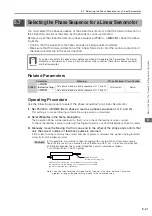
Manually move the Moving Coil in the direction of the cable and check the value of the
feedback pulse counter in the Operation Panel to confirm that it is counting up.
If the pulses are counted up, the forward direction of the Linear Servomotor is the same as the count-
up direction of the linear encoder.
5.
If the feedback pulse counter counts down, set a phase-B lead as a phase sequence of
U, V, and W (Pn080 = n.
1
) and turn the power supply OFF and ON again.
6.
If necessary, return Pn000 = n.
X (Direction Selection) to its original setting.
This concludes the procedure to set the phase sequence of the Linear Servomotor.
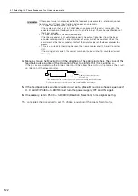
If the correct value is not displayed for the feedback pulse counter, the following condi-
tions may exist. Check the situation and correct any problems.
•
The linear encoder pitch is not correct.
If the scale pitch that is set in Pn282 does not agree with the actual scale pitch, the
expected number of feedback pulses will not be returned. Check the specifications of
the linear encoder.
•
The linear encoder is not adjusted properly.
If the linear encoder is not adjusted properly, the output signal level from the linear
encoder will drop and the correct number of pulses will not be counted. Check the
adjustment of the linear encoder. Contact the manufacturer of the linear encoder for
details.
•
There is a mistake in the wiring between the linear encoder and the Serial Converter
Unit.
If the wiring is not correct, the correct number of pulses will not be counted. Correct
the wiring.
Information
Cable for Linear Servomotor
Moving Coil
If the feedback pulse counter counts up when you manually move the Moving
Coil in the direction of the cable, you have completed the confirmation.


