15.2 Alarm Displays
15.2.2 Troubleshooting Alarms
15-30
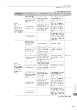
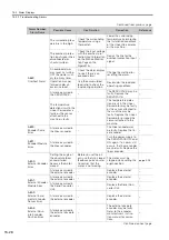
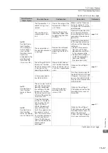
A.bF7:
System Alarm 7
A failure occurred in
the SERVOPACK.
–
Turn the power supply to
the SERVOPACK OFF and
ON again. If an alarm still
occurs, the SERVOPACK
may be faulty. Replace the
SERVOPACK.
–
A.bF8:
System Alarm 8
A failure occurred in
the SERVOPACK.
–
Turn the power supply to
the SERVOPACK OFF and
ON again. If an alarm still
occurs, the SERVOPACK
may be faulty. Replace the
SERVOPACK.
–
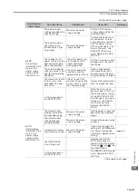
A.C10:
Servomotor Out
of Control
(Detected when
the servo is
turned ON.)
The order of phases
U, V, and W in the
motor wiring is not
correct.
Check the Servomotor
wiring.
Make sure that the Servo-
motor is correctly wired.
–
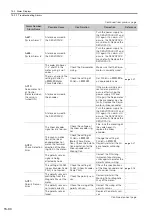
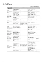
There is an error in the
setting of Pn080 =
n.
X
(Motor
Phase Selection).
Check the setting of
Pn080 = n.
X
.
Set Pn080 = n.
X
to
an appropriate value.
A failure occurred in
the encoder.
–
If the motor wiring is cor-
rect and an alarm still
occurs after turning the
power supply OFF and
ON again, the Servomotor
or linear encoder may be
faulty. Replace the Servo-
motor or linear encoder.
–
A failure occurred in
the SERVOPACK.
–
Turn the power supply to
the SERVOPACK OFF and
ON again. If an alarm still
occurs, the SERVOPACK
may be faulty. Replace the
SERVOPACK.
–
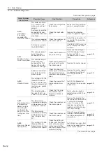
A.C20:
Phase Detection
Error
The linear encoder
signal level is too low.
Check the voltage of
the linear encoder sig-
nal.
Fine-tune the mounting of
the scale head. Or,
replace the linear
encoder.
–
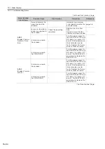
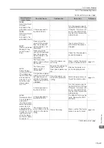
The count-up direc-
tion of the linear
encoder does not
match the forward
direction of the Mov-
ing Coil in the motor.
Check the setting of
Pn080 = n.
X
(Motor Phase Selec-
tion). Check the installa-
tion orientation for the
linear encoder and
Moving Coil.
Change the setting of
Pn080 = n.
X
.
Correctly reinstall the lin-
ear encoder or Moving
Coil.
The polarity sensor
signal is being
affected by noise.
–
Correct the FG wiring.
Implement countermea-
sures against noise for the
polarity sensor wiring.
–
The setting of Pn282
(Linear Encoder Scale
Pitch) is not correct.
Check the setting of
Pn282 (Linear Encoder
Scale Pitch).
Check the specifications
of the linear encoder and
set a correct value.
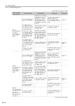
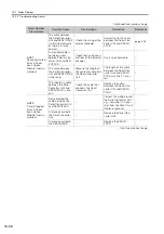
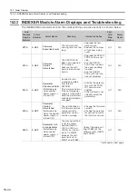
A.C21:
Polarity Sensor
Error
The polarity sensor is
protruding from the
Magnetic Way of the
motor.
Check the polarity sen-
sor.
Correctly reinstall the
Moving Coil or Magnetic
Way of the motor.
–
The polarity sensor is
not wired correctly.
Check the wiring of the
polarity sensor.
Correct the wiring of the
polarity sensor.
–
The polarity sensor
failed.
–
Replace the polarity sen-
sor.
–
Continued on next page.
Continued from previous page.
Alarm Number:
Alarm Name
Possible Cause
Confirmation
Correction
Reference


