2-34
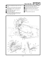
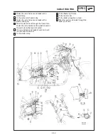
N 20 mm
O Pass the thermo switch lead inside of the
silencer breather hose.
P Place the end of the plastic locking tie as
shown.
Q Inside the motorcycle.
R Fasten the wire harness with a plastic locking
tie.
S Pass the wire harness between the air filter
case groove and frame.
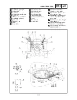
CABLE ROUTING
SPEC
G To the ignition coil.
H Pass the starter cable between the ignition
coil and spark plug lead.
I To the throttle position sensor (TPS).
J To the carburetor.
K To the fuel tank.
L Pass the neutral switch lead, pickup coil lead
and A.C. magneto lead under the ignition coil
lead, thermo switch lead and throttle position
sensor (TPS) lead.
M From the engine.
Содержание XVS6501997
Страница 1: ......
Страница 2: ......
Страница 8: ......
Страница 10: ...GEN INFO ...
Страница 18: ...GEN INFO ...
Страница 20: ...SPEC ...
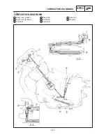
Страница 44: ...2 24 LUBRICATION DIAGRAMS SPEC 1 Crankshaft 2 Oil filter 3 Oil pump ...
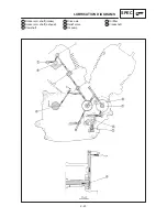
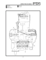
Страница 45: ...2 25 4 Drive axle 5 Main axle 1 Camshaft 2 Rocker arm 3 Starter idle gear LUBRICATION DIAGRAMS SPEC ...
Страница 102: ...INSP ADJ ...
Страница 148: ...4 44 SHIFT SHAFT ENG NOTE 2 Install Shift lever Insert the shift arm 1 between the pins on the shift cam segment ...
Страница 188: ...CARB ...
Страница 198: ...CARB ...
Страница 266: ...CHAS ...
Страница 268: ...ELEC SELF DIAGNOSIS 7 49 TROUBLESHOOTING 7 50 ...
Страница 298: ...E 7 30 SIGNAL SYSTEM ELEC EB806000 SIGNAL SYSTEM CIRCUIT DIAGRAM ...
Страница 320: ...TRBL SHTG ...
Страница 326: ...TRBL SHTG ...


