


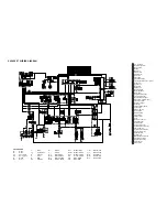

1 A.C. magneto
2 Rectifier / regulator
3 Main switch
4 Battery
5 Main fuse
6 Starter relay
7 Starter motor
8 Relay unit
9 Fuel pump
10
Sidestand switch
11
Throttle position sensor (TPS)
12
Ignitor unit
13
Ignition coil
14
Spark plug
15
Pickup coil
16
Neutral switch
17
Meter assembly
18
Meter light
19
Engine warning light
20
Turn indicator light
21
Neutral indicator light
22
High beam indicator light
23
Front turn signal
24
Rear turn signal
25
Headlight
26
Left handlebar switch
27
Pass switch
28
Dimmer switch
29
Horn switch
30
Clutch switch
31
Turn switch
32
Flasher relay
33
Horn
34
Rear brake switch
35
Tail / brake light
36
Auxiliary light
37
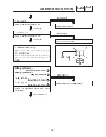
Carburetor heater
38
Carburetor heater relay
39
Thermo switch
40
Carburetor heater fuse
41
Signal system fuse
42
Headlight fuse
43
Ignition fuse
44
Right handlebar switch
45
Front brake switch
46
Engine stop switch
47
Lights switch
48
Start switch
COLOR CODE
B
Black
. . . . .
Br
Brown
. . . .
Ch
Chocolate
. . .
Dg
Dark green
. . .
G
Green
. . . .
Gy
Gray
. . .
L
Blue
. . . . .
Lg
Light green
. . . .
O
Orange
. . . .
P
Pink
. . . . .
R
Red
. . . . .
Sb
Sky blue
. . . .
W
White
. . . .
Y
Yellow
. . . . .
B/ L
Black/ Blue
. . .
B/ W
Black/ White
. .
B/ Y
Black/ Yellow
. . .
Br / B
Brown / Black
. .
Br / L
Brown / Blue
. .
Br / W
Brown / White
.
Br / Y
Brown / Yellow
. .
G / Y
Green / Yellow
. .
L / B
Blue/ Black
. . .
L / R
Blue/ Red
. . .
L / W
Blue/ White
. .
L / Y
Blue/ Yellow
. . .
R/ B
Red / Black
. . .
R/ W
Red / White
. .
R/ Y
Red / Yellow
. . .
XVS650 ’97 WIRING DIAGRAM
Содержание XVS6501997
Страница 1: ......
Страница 2: ......
Страница 8: ......
Страница 10: ...GEN INFO ...
Страница 18: ...GEN INFO ...
Страница 20: ...SPEC ...
Страница 44: ...2 24 LUBRICATION DIAGRAMS SPEC 1 Crankshaft 2 Oil filter 3 Oil pump ...
Страница 45: ...2 25 4 Drive axle 5 Main axle 1 Camshaft 2 Rocker arm 3 Starter idle gear LUBRICATION DIAGRAMS SPEC ...
Страница 102: ...INSP ADJ ...
Страница 148: ...4 44 SHIFT SHAFT ENG NOTE 2 Install Shift lever Insert the shift arm 1 between the pins on the shift cam segment ...
Страница 188: ...CARB ...
Страница 198: ...CARB ...
Страница 266: ...CHAS ...
Страница 268: ...ELEC SELF DIAGNOSIS 7 49 TROUBLESHOOTING 7 50 ...
Страница 298: ...E 7 30 SIGNAL SYSTEM ELEC EB806000 SIGNAL SYSTEM CIRCUIT DIAGRAM ...
Страница 320: ...TRBL SHTG ...
Страница 326: ...TRBL SHTG ...


