4-56
A
B
CRANKSHAFT AND CONNECTING RODS
ENG
*****************************************************
NOTE:
NOTE:
CAUTION:
*****************************************************
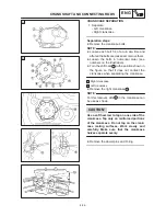
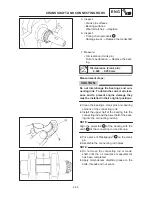
CRANKCASE SEPARATION
1. Separate:
Left crankcase
Right crankcase
Separation steps:
Remove the crankcase bolts.
Loosen each bolt 1 / 4 of a turn at a time and
after all the bolts are loosened, remove them.
Loosen the bolts in numerical order (see
numbers on the illustration).
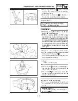
Turn the shift cam
15
to the position shown in
the figure so that it does not contact the
crankcase when separating the crankcase.
A Right crankcase
B Left crankcase
Remove the right crankcase
16
.
For this removal, slits
a
in the crankcase can
be use as shown.
Use a soft hammer to tap on one side of the
crankcase. Tap only on reinforced portions
of the crankcase. Do not tap on the crank-
case mating surfaces. Work slowly and
carefully. Make sure that the crankcase
halves separate evenly.
Remove the dowel pins and O-ring.
Содержание XVS6501997
Страница 1: ......
Страница 2: ......
Страница 8: ......
Страница 10: ...GEN INFO ...
Страница 18: ...GEN INFO ...
Страница 20: ...SPEC ...
Страница 44: ...2 24 LUBRICATION DIAGRAMS SPEC 1 Crankshaft 2 Oil filter 3 Oil pump ...
Страница 45: ...2 25 4 Drive axle 5 Main axle 1 Camshaft 2 Rocker arm 3 Starter idle gear LUBRICATION DIAGRAMS SPEC ...
Страница 102: ...INSP ADJ ...
Страница 148: ...4 44 SHIFT SHAFT ENG NOTE 2 Install Shift lever Insert the shift arm 1 between the pins on the shift cam segment ...
Страница 188: ...CARB ...
Страница 198: ...CARB ...
Страница 266: ...CHAS ...
Страница 268: ...ELEC SELF DIAGNOSIS 7 49 TROUBLESHOOTING 7 50 ...
Страница 298: ...E 7 30 SIGNAL SYSTEM ELEC EB806000 SIGNAL SYSTEM CIRCUIT DIAGRAM ...
Страница 320: ...TRBL SHTG ...
Страница 326: ...TRBL SHTG ...


