


4-12
CYLINDER HEADS
ENG
NOTE:
NOTE:
*****************************************************
*****************************************************
NOTE:
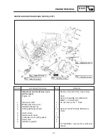
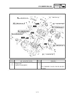
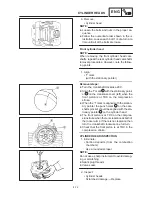
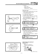
6. Remove:
S
Cylinder head
D
Loosen the bolts and nuts in the proper se-
quence.
D
Follow the numerical order shown in the il-
lustration. Loosen each bolt 1 / 4 of a turn at a
time until all of the bolts are loose.
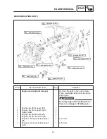
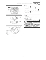
Front cylinder head
When removing the front cylinder head cam-
shafts, repeat the rear cylinder head camshafts
removal procedures. However, note the follow-
ing points.
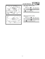
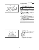
1. Align:
S
“I” mark
(with the stationary pointer)
Removal steps:
D
Turn the crankshaft clockwise 290
_
.
D
Align the “I” mark
a
with the stationary point-
er
b
on the crankcase cover (left) when the
front piston is at TDC on the compression
stroke.
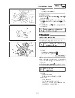
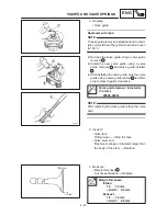
D
When the “I” mark is aligned with the station-
ary pointer the punch mark
c
on the cam-
shaft sprocket should be aligned with the sta-
tionary pointer
d
on the cylinder head.
D
The front piston is at TDC on the compres-
sion stroke when there is clearance at both of
the rocker arms. If there is no clearance then
turn the crankshaft clockwise one full turn.
D
Check that the front piston is at TDC in the
compression stroke.
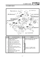
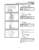
CYLINDER HEAD INSPECTION
1. Eliminate:
S
Carbon deposits (from the combustion
chambers)
Use a rounded scraper.
Do not use a sharp instrument to avoid damag-
ing or scratching:
D
Spark plug threads
D
Valve seats
2. Inspect:
S
Cylinder heads
Scratches / damage
Replace.
Содержание XVS6501997
Страница 1: ......
Страница 2: ......
Страница 8: ......
Страница 10: ...GEN INFO ...
Страница 18: ...GEN INFO ...
Страница 20: ...SPEC ...
Страница 44: ...2 24 LUBRICATION DIAGRAMS SPEC 1 Crankshaft 2 Oil filter 3 Oil pump ...
Страница 45: ...2 25 4 Drive axle 5 Main axle 1 Camshaft 2 Rocker arm 3 Starter idle gear LUBRICATION DIAGRAMS SPEC ...
Страница 102: ...INSP ADJ ...
Страница 148: ...4 44 SHIFT SHAFT ENG NOTE 2 Install Shift lever Insert the shift arm 1 between the pins on the shift cam segment ...
Страница 188: ...CARB ...
Страница 198: ...CARB ...
Страница 266: ...CHAS ...
Страница 268: ...ELEC SELF DIAGNOSIS 7 49 TROUBLESHOOTING 7 50 ...
Страница 298: ...E 7 30 SIGNAL SYSTEM ELEC EB806000 SIGNAL SYSTEM CIRCUIT DIAGRAM ...
Страница 320: ...TRBL SHTG ...
Страница 326: ...TRBL SHTG ...


