6-41
HANDLEBAR
CHAS
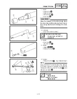
CAUTION:
20 Nm (2.0 m
S
kg)
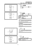
NOTE:
NOTE:
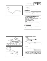
D
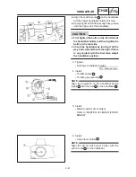
Align the match marks
b
on the handlebar
with the lower handlebar holder bolt hole.
D
Apply a light coat of lithium soap base grease
onto the right end of the handlebar.
D
First tighten the bolts on the front side of
the handlebar holder, and then tighten the
bolts on the rear side.
D
Check the handlebar by turning it all the
way to the left and then to the right. If there
is any contact with the fuel tank, adjust
the handlebar position.
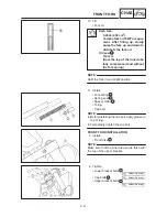
3. Tighten:
S
Nut (lower handlebar holder)
4. Install:
S
Throttle cables
1
S
Throttle grip assembly
2
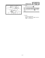
Align the projection on the handlebar switch
(right)
3
with the hole
a
in the handlebar
4
.
5. Install:
S
Master cylinder (front brake)
Refer to “MASTER CYLINDER (FRONT
BRAKE)”.
6. Install:
S
Clutch lever holder
1
Align the slit of clutch lever holder with the
punch mark
a
on the handlebar.
Содержание XVS6501997
Страница 1: ......
Страница 2: ......
Страница 8: ......
Страница 10: ...GEN INFO ...
Страница 18: ...GEN INFO ...
Страница 20: ...SPEC ...
Страница 44: ...2 24 LUBRICATION DIAGRAMS SPEC 1 Crankshaft 2 Oil filter 3 Oil pump ...
Страница 45: ...2 25 4 Drive axle 5 Main axle 1 Camshaft 2 Rocker arm 3 Starter idle gear LUBRICATION DIAGRAMS SPEC ...
Страница 102: ...INSP ADJ ...
Страница 148: ...4 44 SHIFT SHAFT ENG NOTE 2 Install Shift lever Insert the shift arm 1 between the pins on the shift cam segment ...
Страница 188: ...CARB ...
Страница 198: ...CARB ...
Страница 266: ...CHAS ...
Страница 268: ...ELEC SELF DIAGNOSIS 7 49 TROUBLESHOOTING 7 50 ...
Страница 298: ...E 7 30 SIGNAL SYSTEM ELEC EB806000 SIGNAL SYSTEM CIRCUIT DIAGRAM ...
Страница 320: ...TRBL SHTG ...
Страница 326: ...TRBL SHTG ...


