7-2
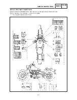
SWITCH INSPECTION
ELEC
NOTE:
SWITCH INSPECTION
SWITCH INSPECTION
Use a pocket tester to check the terminals for
continuity. If the continuity is faulty as any point,
replace the switch.
Pocket tester:
90890-03112
D
Set the pocket tester to “0” before starting the
test.
D
The pocket tester should be set to the ” 1”
Ω
range when testing the switch for continuity.
D
Turn the switch on and off a few times when
checking it.
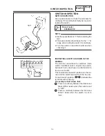
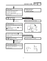
INSPECTING A SWITCH SHOWN IN THE
MANUAL
The terminal connections for switches (main
switch, handlebar switch, engine stop switch,
light switch, etc.) are shown in a chart similar to
the one on the left.
This chart shows the switch positions in the col-
umn and the switch lead colors in the top row.
For each switch position, “
” indicates the
terminals with continuity.
The example chart shows that:
1
There is continuity between the “Black and
Black/ White” leads when the switch is set
to “OFF”.
2
There is continuity between the “Red and
Brown” leads when the switch is set to
“ON”.
Содержание XVS6501997
Страница 1: ......
Страница 2: ......
Страница 8: ......
Страница 10: ...GEN INFO ...
Страница 18: ...GEN INFO ...
Страница 20: ...SPEC ...
Страница 44: ...2 24 LUBRICATION DIAGRAMS SPEC 1 Crankshaft 2 Oil filter 3 Oil pump ...
Страница 45: ...2 25 4 Drive axle 5 Main axle 1 Camshaft 2 Rocker arm 3 Starter idle gear LUBRICATION DIAGRAMS SPEC ...
Страница 102: ...INSP ADJ ...
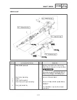
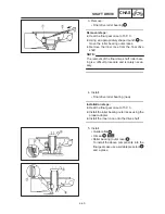
Страница 148: ...4 44 SHIFT SHAFT ENG NOTE 2 Install Shift lever Insert the shift arm 1 between the pins on the shift cam segment ...
Страница 188: ...CARB ...
Страница 198: ...CARB ...
Страница 266: ...CHAS ...
Страница 268: ...ELEC SELF DIAGNOSIS 7 49 TROUBLESHOOTING 7 50 ...
Страница 298: ...E 7 30 SIGNAL SYSTEM ELEC EB806000 SIGNAL SYSTEM CIRCUIT DIAGRAM ...
Страница 320: ...TRBL SHTG ...
Страница 326: ...TRBL SHTG ...


