2-29
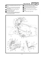
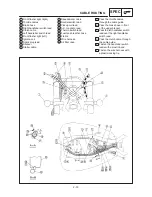
1 Frame bracket
2 Wire harness
3 Fuse box
4 Battery positive (+) lead
5 Spark plug lead
6 Starter cable
7 Right handlebar switch lead
8 Brake hose
9 Throttle cables
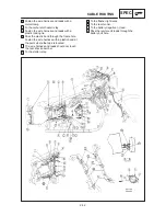
10
Thermo switch lead
11
Flasher light relay
CABLE ROUTING
SPEC
12
Starter relay
13
Carburetor heater relay
14
Neutral switch lead
15
Pickup coil lead
16
A.C. magneto lead
17
Battery negative (–) lead
18
Starter motor lead
19
Starting circuit cut-off relay
20
Fuel tank breather hose
21
Speedometer cable
22
Ignitor unit
A Pass the tail/brake light lead
between the frame bracket and
battery box.
B Fasten the tail/brake light lead
with a battery band. Do not
pinch the harness and tail/
brake light lead.
C To the ignition coil.
D The end of the plastic locking
tie should face towards the
under the handlebar.
Содержание XVS6501997
Страница 1: ......
Страница 2: ......
Страница 8: ......
Страница 10: ...GEN INFO ...
Страница 18: ...GEN INFO ...
Страница 20: ...SPEC ...
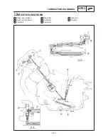
Страница 44: ...2 24 LUBRICATION DIAGRAMS SPEC 1 Crankshaft 2 Oil filter 3 Oil pump ...
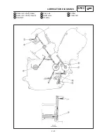
Страница 45: ...2 25 4 Drive axle 5 Main axle 1 Camshaft 2 Rocker arm 3 Starter idle gear LUBRICATION DIAGRAMS SPEC ...
Страница 102: ...INSP ADJ ...
Страница 148: ...4 44 SHIFT SHAFT ENG NOTE 2 Install Shift lever Insert the shift arm 1 between the pins on the shift cam segment ...
Страница 188: ...CARB ...
Страница 198: ...CARB ...
Страница 266: ...CHAS ...
Страница 268: ...ELEC SELF DIAGNOSIS 7 49 TROUBLESHOOTING 7 50 ...
Страница 298: ...E 7 30 SIGNAL SYSTEM ELEC EB806000 SIGNAL SYSTEM CIRCUIT DIAGRAM ...
Страница 320: ...TRBL SHTG ...
Страница 326: ...TRBL SHTG ...

