3-5
A
B
VALVE CLEARANCE ADJUSTMENT
INSP
ADJ
*****************************************************
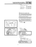
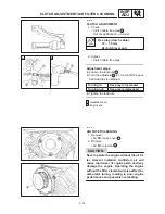
8. Remove:
S
Camshaft sprocket covers
1
9. Remove:
S
Timing plug
1
S
Straight plug
2
10. Measure:
S
Valve clearance
Out of specification
Adjust.
Valve clearance (cold):
Intake valve:
0.07 X 0.12 mm
Exhaust valve:
0.12 X 0.17 mm
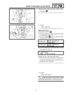
Measuring steps:
D
Turn the crankshaft clockwise with a wrench.
D
Align the camshaft sprocket mark
a
with the
stationary pointer
b
on the cylinder head.
When the mark is aligned with the pointer, the
piston is at Top Dead Center (TDC).
D
Check the front / rear cylinder timing mark
c
on the rotor. If necessary, turn the crankshaft
to align the timing mark with the pointer
d
on
the AC magneto cover.
A For rear cylinder (“TI” mark)
B For front cylinder (“I” mark)
Содержание XVS6501997
Страница 1: ......
Страница 2: ......
Страница 8: ......
Страница 10: ...GEN INFO ...
Страница 18: ...GEN INFO ...
Страница 20: ...SPEC ...
Страница 44: ...2 24 LUBRICATION DIAGRAMS SPEC 1 Crankshaft 2 Oil filter 3 Oil pump ...
Страница 45: ...2 25 4 Drive axle 5 Main axle 1 Camshaft 2 Rocker arm 3 Starter idle gear LUBRICATION DIAGRAMS SPEC ...
Страница 102: ...INSP ADJ ...
Страница 148: ...4 44 SHIFT SHAFT ENG NOTE 2 Install Shift lever Insert the shift arm 1 between the pins on the shift cam segment ...
Страница 188: ...CARB ...
Страница 198: ...CARB ...
Страница 266: ...CHAS ...
Страница 268: ...ELEC SELF DIAGNOSIS 7 49 TROUBLESHOOTING 7 50 ...
Страница 298: ...E 7 30 SIGNAL SYSTEM ELEC EB806000 SIGNAL SYSTEM CIRCUIT DIAGRAM ...
Страница 320: ...TRBL SHTG ...
Страница 326: ...TRBL SHTG ...


