


4-62
CRANKSHAFT AND CONNECTING RODS
ENG
NOTE:
NOTE:
NOTE:
NOTE:
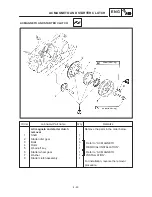
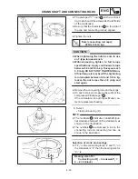
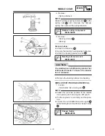
CRANKSHAFT INSTALLATION
1. Attach:
Main journal bearings
1
Attach the main journal bearing to the plane
bearing installer/remover
2
middle driven
shaft bearing driver
3
.
Align the projection
a
on the bearing with the
projection
b
and slot
c
on the special tools.
Plane bearing installer / remover:
90890-04074
Middle driven shaft bearing driver:
90890-04058
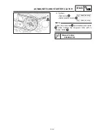
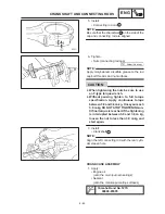
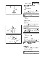
2. Install:
Main journal bearings
1
Align the projection
a
on the bearing with the
slit
b
on the crankcase.
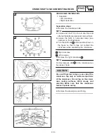
3. Install:
Connecting rod bearings
1
Align the projection
a
of the bearings with
the notches
b
in the connecting rod cap.
Install each bearing in its original place.
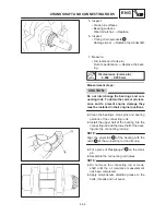
4. Install:
Connecting rods
1
The stamped “Y” mark
a
on the connecting
rods should face towards the left side of the
crankcase.
Install each connecting rod in its original
place.
Содержание XVS6501997
Страница 1: ......
Страница 2: ......
Страница 8: ......
Страница 10: ...GEN INFO ...
Страница 18: ...GEN INFO ...
Страница 20: ...SPEC ...
Страница 44: ...2 24 LUBRICATION DIAGRAMS SPEC 1 Crankshaft 2 Oil filter 3 Oil pump ...
Страница 45: ...2 25 4 Drive axle 5 Main axle 1 Camshaft 2 Rocker arm 3 Starter idle gear LUBRICATION DIAGRAMS SPEC ...
Страница 102: ...INSP ADJ ...
Страница 148: ...4 44 SHIFT SHAFT ENG NOTE 2 Install Shift lever Insert the shift arm 1 between the pins on the shift cam segment ...
Страница 188: ...CARB ...
Страница 198: ...CARB ...
Страница 266: ...CHAS ...
Страница 268: ...ELEC SELF DIAGNOSIS 7 49 TROUBLESHOOTING 7 50 ...
Страница 298: ...E 7 30 SIGNAL SYSTEM ELEC EB806000 SIGNAL SYSTEM CIRCUIT DIAGRAM ...
Страница 320: ...TRBL SHTG ...
Страница 326: ...TRBL SHTG ...


